The DPS turbopumps and roughing pumps require cooling water to operate. This is supplied by the magnet LCW system in S20 which is fed by CT 1202 cooling tower and LCW pumps in S20.
If the cooling tower is off, but the LCW pumps remain on, then the DPS pumps can be kept on if there is no vacuum load on the system since they do not produce much heat.
If the LCW pumps are shut off without warning, the roughing pumps will automatically turn themselves off (they contain a water flow rate sensor), but the turbopumps do not. If the DPS watcher is running then turbos on US1, US2, DS1, and DS2 stages will be shut off automatically when the roughing pumps stop. US3 and US4 turbos will stay on until a temperature sensor trips them off.
In principal there is no risk to the system in the case of an unexpected water outage, but it is good practice to manually prepare for such an outage to remove the chance of vacuum issues or overheating.
Step-by-step guide
- Ensure the DPS Watcher is running
- Use this procedure to stop the DPS pumps: Turning off Differential Pumping System (DPS)
- After the LCW is restored:
- Check that water is flowing to the DPS system: From the "DPS Full Schematic", click on a roughing pump icon, then "More...". Confirm the water flow reading is >0 L/min. Nominal is 1.3 to 2.1 L/min.
- Use this procedure to restart the DPS pumps: Restarting DPS pumps#StartingorRestartingtheDPSpumpswhenthebeamlineisundervacuum
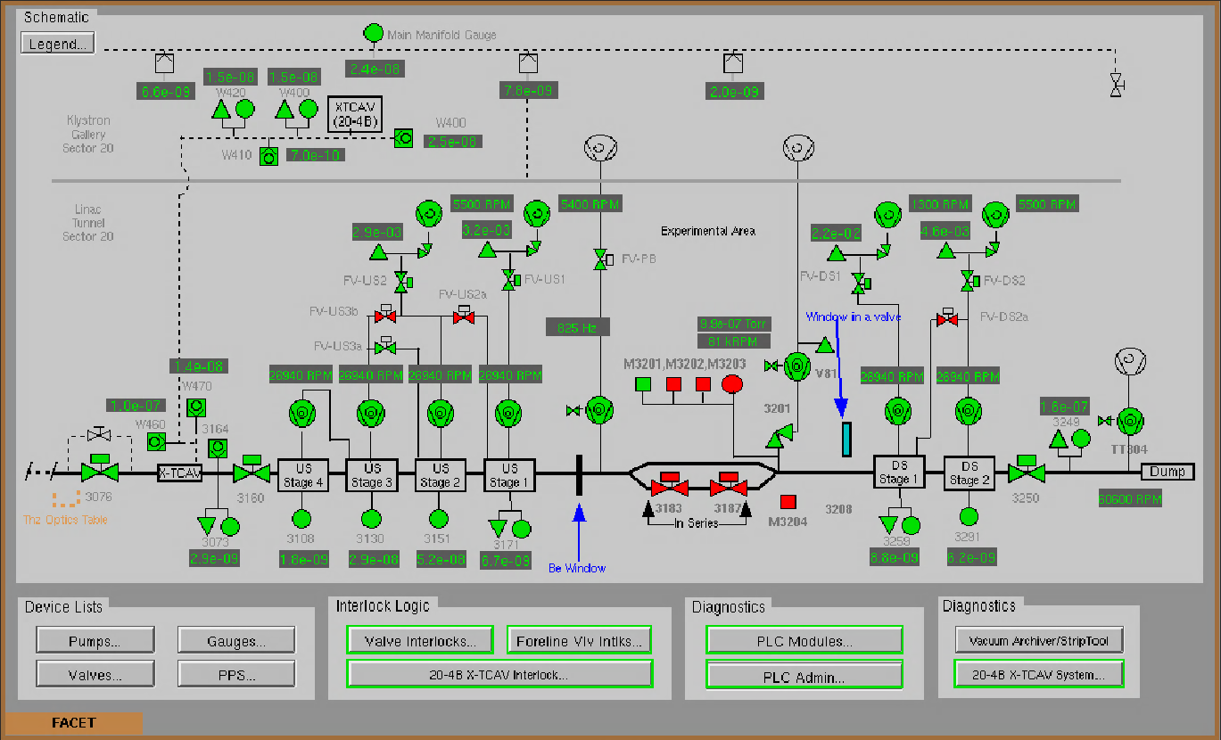
- Confirm the S20 vacuum is returned to the nominal state, as shown below:
DPS under nominal conditions
Layout of the LCW system feeding the DPS pumps
Cooling water for the DPS system is provided by the same LCW water that cools the magnets.
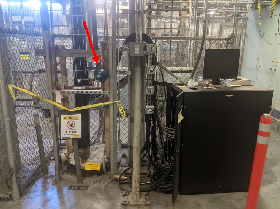
The DPS pumps require the LCW water pressure to be reduced from nominal LCW pressure of ~180psi to around ~60psi. This is done by a pressure regulator in the gallery at penetration 20-10 - pointed at in the image below. The water is transported down the penetration through the insulated pipe. Note that the inline valve to the lower left of the regulator should be open.
In the tunnel at Pen. 20-10, the water is split off towards the upstream and downstream DPS systems.
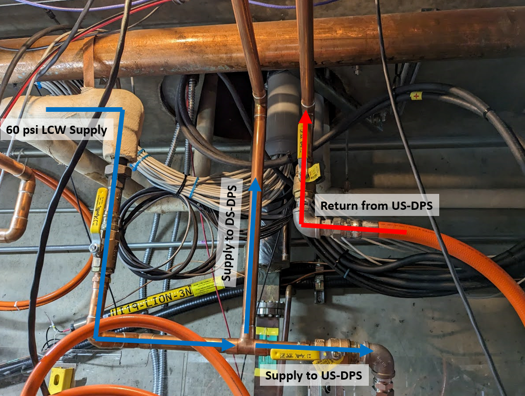
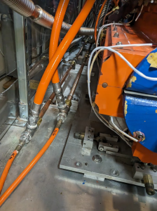
Water flows in parallell to each of the turbos/roughing pumps on each side of the DPS, flowing from a supply manifold, through the pumps, then back to the return manifold. Upstream and downstream manifolds are shown below.
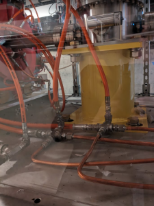
The return feeds back into the main return water manifold on the tunnel ceiling.
Related articles