Two new detectors EPIX10KA2M and EPIX10KAQUAD are composed from EPIX10KA modules.
Content
Geometry
Plots and comments from Chris Kenny
Comments on epix10ka2m geometry from Chris Kenney
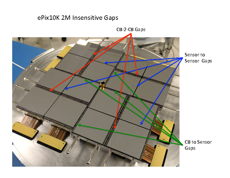
Kenney, Christopher J. 2018-11-12, 2:26 PM

Guide tube is 7mm outer diameter
We added polyimide tape that was 150 microns thick before application
to the tube.

But a decent estimate would be the mechanical edge-to-edge orthogonal
separation between sensor edges 7.3 mm.
We need to add about 1 mm for the guard rings on each sensor

So the orthogonal gap between active pixels on opposing quads across
the beam guide tube should be 8.3 mm

====
Kenney, Christopher J. 2018-11-12, 4:41 PM Blaj, Gabriel;Dubrovin, Mikhail;Kwiatkowski, Maciej

Very rough estimate of the gaps
There are 3 types of gaps
All are active pixel to active pixel
sensor to sensor ~ 1.6 mm
CB to CB ~ 6.4 mm
sensor to CB ~ 3.9 mm

====
CB = Carrier Board edges
Full camera image below
epix10ka2m-insensitive-gaps.pdf
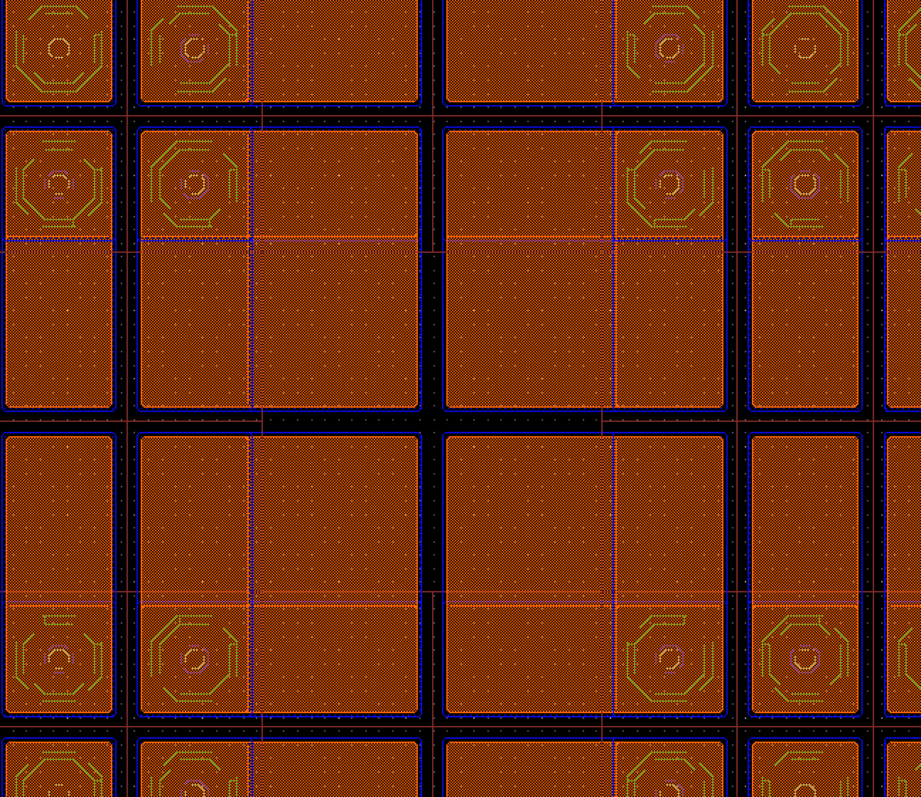
The internal gap between ASICs in sensor,
pixel size 100 x 225 microns in area in both directions.
Comments on orientation of epix10ka2m parts from Matt
Weaver, Matt
Tue 10/9, 3:07 PMO'Grady, Paul Christopher;Dubrovin, Mikhail;Damiani, Daniel S.
Also, here's some description of the nominal geometry.
Pay close attention to the last part that describes the positioning of
ASICs within an "element".  I think this might be different than before.
-Matt

  //
  //   Hard code the array's geometry for now
  //
  //  (Epix10ka2m)
  //         |
  //  Quad 3 | Quad 0      Quad 1 is rotated  90d clockwise
  //  -------+--------     Quad 2 is rotated 180d clockwise
  //  Quad 2 | Quad 1      Quad 3 is rotated 270d clockwise
  //         |
  //
  //  (Quad 0)
  //         |
  //  Elem 0 | Elem 1
  //  -------+--------     No rotations
  //  Elem 2 | Elem 3
  //         |
  //
  //  (Elem 0)
  //         |
  //  ASIC 0 | ASIC 3
  //  -------+--------     No rotations
  //  ASIC 1 | ASIC 2
  //         |
References
Overview
Content Tools