Issues
Issues to consider:
- (done) Move to Rogue 6: v 1.0.0
- current configuration time is long at 34s
- some progress on this: now 10s according to Ric (check that we're down to 2-3 seconds that rogue sees?)
- fiber-power monitoring on the detector side and kcu1500
- not there yet on march 22, 2024
- have to manually lock the lanes between ASICs and managing FPGA by running 1000 events: feels awkward-ish
- what does epixHR do?
- not all lanes in an ASIC lock (can perhaps be fixed with improved delay settings)
- most have 3-5 lanes that don't function or are unstable (out of 24)
- data is currently scrambled (not natural order)
- ric is descrambling ASICS in software, but would like to move to hardware
- (done) remove epixViewer imports in _Root.py
- add batcherEventBuilder to kcu1500
- use Lcls2EpixHrXilinxKcu1500Pgp4_10Gbps, which contains a BEB
- make the ePixM devGui compatible
- remove 8 bytes of null padding between timing header elements
- fix set-registers-before-each-charge-injection-event issue
- Implement FPGA registers to rearm ASICs on each event when
testregister is true?
- Implement FPGA registers to rearm ASICs on each event when
- (done) Split prepareChargeInjection() into 2 functions, the first taking first and last column (as now) and the second taking a 384 element numpy array (e.g., setupChargeInjection(self, asicIndex, lane_selected, pulserValue))
- Since the scan work, normal data taking runs now see dropped and short frames from ASIC 0
- DAQ has no environmental monitoring support as yet
- needs board re-spin (boards in layout on March 22, 2024)
- will epixM automatically increase charge with each injection pulse like epixHR? Dionisio thinks probably not (will double-check with Lorenzo).
- zmq server port gone with rogue6? needs to be re-added?
- need to know common-mode "bank" info
- each lane?
- other structures for ADC?
Miscellaneous Info
Asic readout order:
The ASICs are in this format. ASIC 0 and 1 rotated 180 degree (viewed looking at the sensor):
0 1
3 2
Currently running on drp-neh-cmp003 and using (perhaps incorrectly) tdetsim.service.
Auto-ranging, cannot be run in fixed-range mode (maybe Lorenzo is thinking about this?)
GitHub repo: https://github.com/slaclab/epix-hr-m-320k (currently using branch tempRelease)
currently has 4 ASICs in a 2x2 configuration (one piece of silicon). the size of the ASIC is 192*384 columns (more than twice as big as EpixHR ASIC)
each ASIC is its own lane
firmware defaults to LCLS-II timing
Need to ask Chris Kenney or Lorenzo about precise panel geometries so Mikhail can support the geometry in psana2
need this setting in devGui under "Root":
![]()
3 means 168MHz clock, and the 4 1's initialize (includes a reset plus configuration) the ASICs, which includes loading config files: the config files that are used are in config/ePixHRM320k_ASIC_u1_PLLBypass.yml (and u2,u3,u4 for other ASICs). Currently the 4 configurations are identical, apart from a module name. Also configures the firmware of a single "managing" FPGA (e.g. batching event-builder).
Issue: the serial links between the managing FPGA and the ASICs don't always lock until a number of frames have been transmitted (may want to fix this more robustly in the long-term). Short-term workaround: call root.hwTrigger(frames, rate) for ~1000 frames at rate 1000 (1kHz).
Currently the data needs to be descrambled in software. There is a plan to eventually descramble in firmware.
Plan: run the software/notebook/maximumRateTest.ipynb
Introductory script
### Setup the library ###
import pyrogue as pr
import os, sys
import matplotlib.pyplot as plt
import time
import datetime
import numpy as np
import math
import pprint
import inspect
top_level=f'{os.getcwd()}/../'
rootTopLevel = top_level+'script/'
pr.addLibraryPath( rootTopLevel )

import setupLibPaths

import ePix320kM as devBoard

args = None

# ONLY RUN ONCE!
# Defining root
root =  devBoard.Root(
        top_level  = rootTopLevel,
        dev        = '/dev/datadev_0',
        pollEn     = False,
        initRead   = True,
        serverPort = 9099,
        pciePgpEn  = True,
)
root.start()

# example showing a read
AxiVersion = root.Core.AxiVersion
print ( '###################################################')
print ( '#             Firmware Version                    #')
print ( '###################################################')
AxiVersion.printStatus()
print ( '###################################################')

# Useful short names
APP  = root.App
AXIV = root.Core.AxiVersion
ASICTOP = APP.AsicTop
TRIG = ASICTOP.TriggerRegisters
ASIC0 = APP.Mv2Asic[0]
ASIC1 = APP.Mv2Asic[1]
ASIC2 = APP.Mv2Asic[2]
ASIC3 = APP.Mv2Asic[3]
HSDAC = APP.Dac.FastDac
PKREG = [None] * 4
PKREG[0] = ASICTOP.DigAsicStrmRegisters0
PKREG[1] = ASICTOP.DigAsicStrmRegisters1
PKREG[2] = ASICTOP.DigAsicStrmRegisters2
PKREG[3] = ASICTOP.DigAsicStrmRegisters3
BATCHER0 = ASICTOP.BatcherEventBuilder0
BATCHER1 = ASICTOP.BatcherEventBuilder1
BATCHER2 = ASICTOP.BatcherEventBuilder2
BATCHER3 = ASICTOP.BatcherEventBuilder3
DEBUG0 = root._dbg[0]
DEBUG1 = root._dbg[1]
DEBUG2 = root._dbg[2]
DEBUG3 = root._dbg[3]
DATARCV0 = root.DataReceiver0
DATARCV1 = root.DataReceiver1
DATARCV2 = root.DataReceiver2
DATARCV3 = root.DataReceiver3
FULLRATERCV0 = root.fullRateDataReceiver[0]
FULLRATERCV1 = root.fullRateDataReceiver[1]
FULLRATERCV2 = root.fullRateDataReceiver[2]
FULLRATERCV3 = root.fullRateDataReceiver[3]
DAC = APP.Dac
REGCTRL = ASICTOP.RegisterControlDualClock

# Configure clock to 168 MHz and configures all ASICS
root.InitASIC([3,1,1,1,1])

# disable some software rogue data receivers
root.disableAndCleanAllFullRateDataRcv()
root.enableDataRcv(False)
root.enableDataDebug(False)

#run some triggers and exercise lanes and locks
frames = 5000
rate = 1000

root.hwTrigger(frames, rate)

#get locked lanes
root.getLaneLocks()

#Enable data receivers and run some triggers
root.enableDataRcv(True)
root.enableAllAsics(True)
root.Trigger() # one event via software trigger

# Obtain descrambled single frame data from ASICs from DataReceiver. Data receiver is down sampled.
root.printDataReceiverStatus()

frame = [None for i in range(4)]
for asicIndex in range(4):
    frame[asicIndex] = getattr(root, f"DataReceiver{asicIndex}").Data.get()

#frame dimensions
for asicIndex in range(root.numOfAsics):
    print(np.shape(frame[asicIndex]))

#plot image
plt.subplots(2,2,figsize=(17,17))
for asicIndex in range(root.numOfAsics):
    if asicIndex == 3 :
        plt.subplot(2,2,3)
    elif asicIndex == 2 :
        plt.subplot(2,2,4)
    else :
        plt.subplot(2,2,asicIndex+1)

    if np.shape(frame[asicIndex])[0] != 1 :
        plt.imshow(frame[asicIndex])
        plt.xlabel("ASIC {}".format(asicIndex))
        plt.colorbar()
    else :
        plt.xlabel("ASIC {}: No data".format(asicIndex))
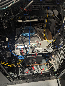
Teststand: (timing is left fiber, registers are on middle MPO8 fiber, data is on right MPO8 fiber)
To lock the lanes:
App->AsicTop->TriggerRegisters→SetAutoTrigger (set to 1000 and hit enter)
numberTrigger set to 5000
StartautoTrigger (exec)
Do "Read All" at the bottom and check that AcqCount and DaqCount are 5000
StopTriggers
View state of locks with App→SspMonGrp[0:3] look at "Locked" register. Total of 24 lanes in each asic (should be 0xffffff). Can still run even if not all links are locked: disable lanes that are not functioning. Saw between 0 and 6 lanes not locked for asics 0-3. Mostly reproducible failing lane numbers.
App->AsicTop→DigAsicStrmRegisters[0:3] set "DisableLane" to turn off non-locked lanes. A single unlocked lane that is not disabled will prevent frames from being transmitted by firmware.
Enable the software receivers via DataReceiver[0:3] with RxEnable. Hit "Trigger" to generate one software trigger. In principle can view an image with DisplayViewer[0:3], but saw a pydm error when we tried this.
To run with XPM triggers, go to the usual TriggerEventManager→TriggerEventBuffer[1] and set "Partition" to the readout group: this is the DAQ trigger. TriggerEventBuffer[0] is the Run Trigger.
To see trigger counts go to AsicTop→TriggerRegisters and EXEC "SetTimingTrigger" and then do a "Read All" to watch for counters to increment (AcqCount and DaqCount). Did two things: set TriggerEventBuffer[0] (the run trigger) to also fire on the readout group and set AsicTop->TriggerRegisters→PgpTrigEn to True and then we saw it count. AcqCount counts run triggers, and the DaqCount counts daq triggers. Can see it in the DataReceiver "FrameCount"
Dawood writes: Chris, I just noticed that the batchers have the register Bypass set to 1. That needs to become 0 when we using timing from the timing fiber for all 4 ASICS.
Fiber Requirements for Prototype
For MFX beam time Phil requested 6 fiber pairs plus spares, eventually 24: ECS-3992 - Getting issue details... STATUS
cpo has a message from Omar dated Oct. 2, 2023 that says there are 6 fiber pairs between room 208 and mfx.
Dionisio wrote about the fiber pair count requirement for the prototype detector:
Looking at the git repo https://github.com/slaclab/epix-hr-m-320k I would think that the minimum number of fibers is 7 but @Dawood Alnajjar please confirm this
Lane[0].VC[0] = Data[0]
Lane[1].VC[0] = Data[1]
Lane[2].VC[0] = Data[2]
Lane[3].VC[0] = Data[3]

Lane[5].VC[0] = SRPv3
Lane[5].VC[1] = software trigger (ssiCmd)
Lane[5].VC[2] = XVC
-Lane[6].VC[0] = slow monitoring[1:0]
-    [1] = Power and Communication Board
-    [0] = Digital Board


Lane[11] = LCLS-II Timing
Running devGui
Using XilinxKcu1500Pgp4_10Gbps mcs files from pgp-pcie-apps GitHub repo
(need to run from the "script" directory at the moment) "python script/devGui.py --pciePgpEn 1 --boardType XilinKcu1500". or to run with via the zmq port: "python devGui.py --serverPort 9200 --pciePgpEn 1" (zmq port defaults to 9100, but that port was in use in the test stand). or to ignore the data streams: "python devGui.py --boardType XilinxKcu1500 --dev /dev/datadev_0 --pciePgpEn 1 --justCtrl 1"
For kcu1500 devGui use pgp-pcie-apps directory and run "python scripts/PgpMonitor.py --numLane 8 --boardType Kcu1500". Currently (April 1, 2024) this still requires rogue5.
Pedestal Scans and Charge Injection
(documents from Dionisio, Lorenzo and Dawood)
ePixM: gain modes, Charge Injection, Charge injection with python using helper functions
(from Conny on Jan. 24 2024)
As you mentioned, this detector only has one gain mode, which is an outranging mode. However, the idea is to create two additional “fixed gain modes” currently referred to as soft fixed modes. These modes are created by changing the switching point of the auto-ranging mode. So for the SL, the switching point is moved below the baseline and we are always switched, and for SH the switching point is all the way up the dynamic range, so the detector never switches. As such, unlike the current generation of epix detectors which moves between gain modes by changing the tr_bit and the pixel config matrix value (ePixM do not contain registers that change the functionality of the pixels), the soft gain modes will be moved into by changing the following registers (Ric says these registers are settable per-asic):
Mode | CompTH_ePixM | Precharge_DAC_ePixM | |
Auto-gain | 12 | 45 | |
Soft High | 0 | 45 | |
Soft Low | 63 | 50 | |
Here the CompTH_ePixM register defines the location of the switching point. The values of these registers are subject to change as we start to characterize the detector and might change a bit when we optimize the performance. So, for a pedestal script, we would likely want to cycle through these settings and collect ~2000 frames in each cycle to determine their relative pedestal maps (AHL, SH,SM).
From Dionisio: Speaking with Lorenzo, the Precharge_DAC changes with the pixel mode. So it does not get to be scanned but it is set intentionally at the same time as the threshold is set. Here (https://confluence.slac.stanford.edu/display/ppareg/ePixM%3A+gain+modes) are some suggested values.
For the charge injection, that is also a new beast for this detector. Unlike the previous detectors, we are not injecting an external signal, but switching an already charged capacitor. This has been implemented in a way that charge injection occurs for all pixels in column in one go. I talked to Dionisio and Lorenzo and they will ask Dawood to provide some documentation on how you make charge injection happen for this detector. Also, unlike the previous detectors where we performed charge injection on a central pixel, with no charge injection on its neighbor, and then cycled through all pixels so they all receive charge injection, here we will be performing charge injection on a combination of columns simultaneously and stepping through, but Dionisio and Lorenzo wanted to cycle around how to do this and then get back to you.
See Charge injection with python using helper functions.
From Chris: I think for previous detectors charge injection has run in all modes. The actual settings will be tweaked, but it would be good to do the same for epixM, and ideally verify that the pixels do change range when the switching threshold is set somewhere in the middle.
From Dawood: I talked to Lorenzo. Yes, the columns need to be reprogrammed everytime. Meaning that you would need to run the prepareChargeInjection everytime before running a trigger event, even if the columns configuration does not change between the two consecutive trigger events.
April 2024 Beamtime Requirements
*** critical
- will use a new detector for beam time
- *** 5kHz epixM
- run-trigger and daq-trigger patterns:
- 5k,5k
- 5k,120
- 5k,2.5k
- matt provides "divisors-of-5k" script which should still work
- run-trigger and daq-trigger patterns:
- *** timing scans
- (done?) configuration scan
- Looks like cas/epixhr_timing_scan.py should work for the ePixM, too
- (done?) configuration scan
- *** fibers/nodes
- have 11 working fiber pairs and 1 broken one. epixhr uses 3 (2 data 1 timing) epixm uses 5 (4 data 1 timing 1 register)
- cpo submitted Jira to fix broken fiber and add fix cassettes between 208 and src
- need to check that all 11 are working
- Chris Ford is tasked with running timing/data fibers in 208/srcf and by default will use cmp034 for the epixM
- need detector group help going from mezzanine to hutch
- have 11 working fiber pairs and 1 broken one. epixhr uses 3 (2 data 1 timing) epixm uses 5 (4 data 1 timing 1 register)
- *** does psana handle disabled lanes correctly? currently the disabled lanes get a fixed number put in them (lane-number). this may work with Mikhail's.
- tstx00417 in ~tstopr/data/drp/tst/tstx00417/xtc/ runs 313 and 314 but shape may be incorrect.
- (done) run 316 has the data organized as (4, 192, 384). Previously, it was (1, 384, 768).
- cable to see acquisition window on the scope?
- dawood will check
- intensity scans
- done by changing the beam so no work required from daq group
- pedestals
- soft-low
- soft-hi
- threshold in the middle SA
- mikhail will work on "placeholder" infrastructure but there are subtleties that we won't worry about for the beam time
- don't necessarily need calibrated data
- (lower priority) more precisely define how we handle the gain-switching, if at all?
- soft-low (configurable threshold at one extreme)
- soft-high (configurable threshold at the other extreme)
- configurable threshold in the middle
- what are the nominal gains? nominal gain ratio is 4.7
- bit 15 is gain mode, bits 0-14 are data. data bits may be trimmed in the future (13 or 12?)
- (lower priority) charge-injection
- mikhail/ric are putting in placeholder code, but doesn't work: waiting for ASIC/FPGA fix
Detector Interface: DAQ-Segments With Multiple Free-Floating ASICs
*** problem: 1 epixM daq-segment has 4 "panels" ("multi-panel segments") that need geometry
*** need to add new idea: "panels" contained in each segment
Conclusion (mikhail's requirement): if we had a 12-asic epixm detector, then each epixM daq-segment must have "quanta" 4 panels (3 daq-segments total). Agreed! three .xtc files each with shape (4,192,384) but det.raw.raw() reshapes it to (12,192,384). Mikhail
Terminology: segment means daq-segment. What's the terminology for asics in daq-segment? panels, virtual-segments, asics, sub-segments, vsegment? Mikhail suggests we use "panels" for now.
everything stays the same (1 serial number per segment)
except: 1 segment has 4 panels with geometry that is looked up with seg serial#
does it make it easier to reshape (4,192,384) to (384,768) but has variable geom?
- doesn't help. difficulty: breaks rule that all panels are identical
could we add a new "segment" idea where we override the daq-segment-numbers? "panels"
processing of partial detector is important (e.g. daq-segments 2,7)
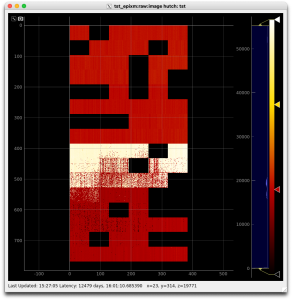
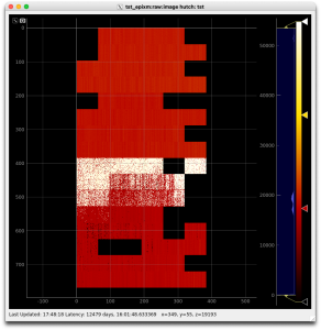
Intermittent ASIC Lanes
A number of the data lanes from the ASICs are intermittent on the device we're testing with (0016778240-0000000000-0000000000-4032267777-3204448280-0177427457-3053453334). After disabling these lanes, the current detector interface provides images in AMI like the lefthand image below. After Dawood adjusted various App.SspMonGrp[*].UsrDlyCfg[*] values, more lanes became reliable (righthand image). This configuration was tested with Run/DAQ triggers set to 100/100, 5000/100, 5000/5000, 5000/2500, and 4000/2000 Hz.
Overview
Content Tools