Issues
Issues to consider:
- (done) Move to Rogue 6: v 1.0.0
- current configuration time is long at 34s
- some progress on this: now 10s according to Ric (check that we're down to 2-3 seconds that rogue sees?)
- fiber-power monitoring on the detector side and kcu1500
- not there yet on march 22, 2024
- (done for the detector as of v1.1.5 of epix-hr-m-320k)
- (done?) have to manually lock the lanes between ASICs and managing FPGA by running 1000 events: feels awkward-ish
- what does epixHR do?
- not all lanes in an ASIC lock (can perhaps be fixed with improved delay settings)
- most have 3-5 lanes that don't function or are unstable (out of 24) for unit 0xbf
- data is currently scrambled (not natural order)
- ric is descrambling ASICS in software, but would like to move to firmware
- (done) remove epixViewer imports in _Root.py
- on May 11, 2024 lost timing link from epixM to xpm7 (had to power cycle). Include Julian's latest link fixes in your firmware.
- need eye-scanning for all transceiver links
- add batcherEventBuilder to kcu1500
- use Lcls2EpixHrXilinxKcu1500Pgp4_10Gbps, which contains a BEB
- make the ePixM devGui compatible
- (done) remove 8 bytes of null padding between timing header elements
- fix set-registers-before-each-charge-injection-event issue
- Implement FPGA registers to rearm ASICs on each event when
testregister is true?
- Implement FPGA registers to rearm ASICs on each event when
- (done) Split prepareChargeInjection() into 2 functions, the first taking first and last column (as now) and the second taking a 384 element numpy array (e.g., setupChargeInjection(self, asicIndex, lane_selected, pulserValue))
- (done) Since the scan work, normal data taking runs now see dropped and short frames from ASIC 0
- DAQ has no environmental monitoring support as yet
- needs board re-spin (boards in layout on March 22, 2024)
- will epixM automatically increase charge with each injection pulse like epixHR? Dionisio thinks probably not (will double-check with Lorenzo).
- (done?) zmq server port gone with rogue6? needs to be re-added?
- need to know common-mode "bank" info
- each lane?
- other structures for ADC?
- v1.1.5 of epix-hr-m-320k introduced per detector instance yaml files, which implies that if a detector is swapped out, either:
- the configDb for the given detector alias must be reinitialized, or
- a different detector alias and configDb instance must be set up
- requires corresponding .cnf changes
Miscellaneous Info
Asic readout order:
The ASICs are in this format. ASIC 0 and 1 rotated 180 degree (viewed looking at the sensor):
0 1
3 2
Currently running on drp-neh-cmp003 and using (perhaps incorrectly) tdetsim.service.
- (done) change to kcu.service
Auto-ranging, cannot be run in fixed-range mode (maybe Lorenzo is thinking about this?)
GitHub repo: https://github.com/slaclab/epix-hr-m-320k (currently using branch tempRelease)
currently has 4 ASICs in a 2x2 configuration (one piece of silicon). the size of the ASIC is 192*384 columns (more than twice as big as EpixHR ASIC)
each ASIC is its own lane
firmware defaults to LCLS-II timing
Need to ask Chris Kenney or Lorenzo about precise panel geometries so Mikhail can support the geometry in psana2
need this setting in devGui under "Root":
![]()
3 means 168MHz clock, and the 4 1's initialize (includes a reset plus configuration) the ASICs, which includes loading config files: the config files that are used are in config/ePixHRM320k_ASIC_u1_PLLBypass.yml (and u2,u3,u4 for other ASICs). Currently the 4 configurations are identical, apart from a module name. Also configures the firmware of a single "managing" FPGA (e.g. batching event-builder).
- As of v1.1.5, InitASIC() is called with 4, 1, 1, 1, 1 where 4 means 'use a default on-board clock configuration'.
- As of v1.1.6, some .yml filenames have changed. Some are now detector specific and so include the digital board's serial number.
Issue: the serial links between the managing FPGA and the ASICs don't always lock until a number of frames have been transmitted (may want to fix this more robustly in the long-term). Short-term workaround: call root.hwTrigger(frames, rate) for ~1000 frames at rate 1000 (1kHz).
Currently the data needs to be descrambled in software. There is a plan to eventually descramble in firmware.
Plan: run the software/notebook/maximumRateTest.ipynb
 DOERING - ePixHRM320k- A detector system for soft x-ray imaging - abstract 2023.pdf
Introductory script (likely out of date):
### Setup the library ###
import pyrogue as pr
import os, sys
import matplotlib.pyplot as plt
import time
import datetime
import numpy as np
import math
import pprint
import inspect
top_level=f'{os.getcwd()}/../'
rootTopLevel = top_level+'script/'
pr.addLibraryPath( rootTopLevel )

import setupLibPaths

import ePix320kM as devBoard

args = None

# ONLY RUN ONCE!
# Defining root
root =  devBoard.Root(
        top_level  = rootTopLevel,
        dev        = '/dev/datadev_0',
        pollEn     = False,
        initRead   = True,
        serverPort = 9099,
        pciePgpEn  = True,
)
root.start()

# example showing a read
AxiVersion = root.Core.AxiVersion
print ( '###################################################')
print ( '#             Firmware Version                    #')
print ( '###################################################')
AxiVersion.printStatus()
print ( '###################################################')

# Useful short names
APP  = root.App
AXIV = root.Core.AxiVersion
ASICTOP = APP.AsicTop
TRIG = ASICTOP.TriggerRegisters
ASIC0 = APP.Mv2Asic[0]
ASIC1 = APP.Mv2Asic[1]
ASIC2 = APP.Mv2Asic[2]
ASIC3 = APP.Mv2Asic[3]
HSDAC = APP.Dac.FastDac
PKREG = [None] * 4
PKREG[0] = ASICTOP.DigAsicStrmRegisters0
PKREG[1] = ASICTOP.DigAsicStrmRegisters1
PKREG[2] = ASICTOP.DigAsicStrmRegisters2
PKREG[3] = ASICTOP.DigAsicStrmRegisters3
BATCHER0 = ASICTOP.BatcherEventBuilder0
BATCHER1 = ASICTOP.BatcherEventBuilder1
BATCHER2 = ASICTOP.BatcherEventBuilder2
BATCHER3 = ASICTOP.BatcherEventBuilder3
DEBUG0 = root._dbg[0]
DEBUG1 = root._dbg[1]
DEBUG2 = root._dbg[2]
DEBUG3 = root._dbg[3]
DATARCV0 = root.DataReceiver0
DATARCV1 = root.DataReceiver1
DATARCV2 = root.DataReceiver2
DATARCV3 = root.DataReceiver3
FULLRATERCV0 = root.fullRateDataReceiver[0]
FULLRATERCV1 = root.fullRateDataReceiver[1]
FULLRATERCV2 = root.fullRateDataReceiver[2]
FULLRATERCV3 = root.fullRateDataReceiver[3]
DAC = APP.Dac
REGCTRL = ASICTOP.RegisterControlDualClock

# Configure clock to 168 MHz and configures all ASICS
root.InitASIC([3,1,1,1,1])

# disable some software rogue data receivers
root.disableAndCleanAllFullRateDataRcv()
root.enableDataRcv(False)
root.enableDataDebug(False)

#run some triggers and exercise lanes and locks
frames = 5000
rate = 1000

root.hwTrigger(frames, rate)

#get locked lanes
root.getLaneLocks()

#Enable data receivers and run some triggers
root.enableDataRcv(True)
root.enableAllAsics(True)
root.Trigger() # one event via software trigger

# Obtain descrambled single frame data from ASICs from DataReceiver. Data receiver is down sampled.
root.printDataReceiverStatus()

frame = [None for i in range(4)]
for asicIndex in range(4):
    frame[asicIndex] = getattr(root, f"DataReceiver{asicIndex}").Data.get()

#frame dimensions
for asicIndex in range(root.numOfAsics):
    print(np.shape(frame[asicIndex]))

#plot image
plt.subplots(2,2,figsize=(17,17))
for asicIndex in range(root.numOfAsics):
    if asicIndex == 3 :
        plt.subplot(2,2,3)
    elif asicIndex == 2 :
        plt.subplot(2,2,4)
    else :
        plt.subplot(2,2,asicIndex+1)

    if np.shape(frame[asicIndex])[0] != 1 :
        plt.imshow(frame[asicIndex])
        plt.xlabel("ASIC {}".format(asicIndex))
        plt.colorbar()
    else :
        plt.xlabel("ASIC {}: No data".format(asicIndex))
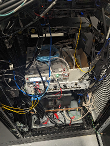
Teststand: (timing is left fiber, registers are on middle MPO8 fiber, data is on right MPO8 fiber)
To lock the lanes:
App->AsicTop->TriggerRegisters→SetAutoTrigger (set to 1000 and hit enter)
numberTrigger set to 5000
StartautoTrigger (exec)
Do "Read All" at the bottom and check that AcqCount and DaqCount are 5000
StopTriggers
View state of locks with App→SspMonGrp[0:3] look at "Locked" register. Total of 24 lanes in each asic (should be 0xffffff). Can still run even if not all links are locked: disable lanes that are not functioning. Saw between 0 and 6 lanes not locked for asics 0-3. Mostly reproducible failing lane numbers.
App->AsicTop→DigAsicStrmRegisters[0:3] set "DisableLane" to turn off non-locked lanes. A single unlocked lane that is not disabled will prevent frames from being transmitted by firmware.
Enable the software receivers via DataReceiver[0:3] with RxEnable. Hit "Trigger" to generate one software trigger. In principle can view an image with DisplayViewer[0:3], but saw a pydm error when we tried this.
To run with XPM triggers, go to the usual TriggerEventManager→TriggerEventBuffer[1] and set "Partition" to the readout group: this is the DAQ trigger. TriggerEventBuffer[0] is the Run Trigger.
To see trigger counts go to AsicTop→TriggerRegisters and EXEC "SetTimingTrigger" and then do a "Read All" to watch for counters to increment (AcqCount and DaqCount). Did two things: set TriggerEventBuffer[0] (the run trigger) to also fire on the readout group and set AsicTop->TriggerRegisters→PgpTrigEn to True and then we saw it count. AcqCount counts run triggers, and the DaqCount counts daq triggers. Can see it in the DataReceiver "FrameCount"
Dawood writes: Chris, I just noticed that the batchers have the register Bypass set to 1. That needs to become 0 when we using timing from the timing fiber for all 4 ASICS.
Fiber Requirements for Prototype
For MFX beam time Phil requested 6 fiber pairs plus spares, eventually 24: ECS-3992 - Getting issue details... STATUS
cpo has a message from Omar dated Oct. 2, 2023 that says there are 6 fiber pairs between room 208 and mfx.
Dionisio wrote about the fiber pair count requirement for the prototype detector:
Looking at the git repo https://github.com/slaclab/epix-hr-m-320k I would think that the minimum number of fibers is 7 but @Dawood Alnajjar please confirm this
Lane[0].VC[0] = Data[0]
Lane[1].VC[0] = Data[1]
Lane[2].VC[0] = Data[2]
Lane[3].VC[0] = Data[3]

Lane[5].VC[0] = SRPv3
Lane[5].VC[1] = software trigger (ssiCmd)
Lane[5].VC[2] = XVC
-Lane[6].VC[0] = slow monitoring[1:0]
-    [1] = Power and Communication Board
-    [0] = Digital Board


Lane[11] = LCLS-II Timing
Running devGui
Using XilinxKcu1500Pgp4_10Gbps mcs files from pgp-pcie-apps GitHub repo
(need to run from the "script" directory at the moment) "python script/devGui.py --pciePgpEn 1 --boardType XilinKcu1500". or to run with via the zmq port: "python devGui.py --serverPort 9200 --pciePgpEn 1" (zmq port defaults to 9100, but that port was in use in the test stand). or to ignore the data streams: "python devGui.py --boardType XilinxKcu1500 --dev /dev/datadev_0 --pciePgpEn 1 --justCtrl 1"
For kcu1500 devGui use pgp-pcie-apps directory and run "python scripts/PgpMonitor.py --numLane 8 --boardType XilinxKcu1500". Currently (April 1, 2024) this still requires rogue5 in ps-4.6.1.
Pedestal Scans and Charge Injection
(documents from Dionisio, Lorenzo and Dawood)
ePixM: gain modes, Charge Injection, Charge injection with python using helper functions
(from Conny on Jan. 24 2024)
As you mentioned, this detector only has one gain mode, which is an outranging mode. However, the idea is to create two additional “fixed gain modes” currently referred to as soft fixed modes. These modes are created by changing the switching point of the auto-ranging mode. So for the SL, the switching point is moved below the baseline and we are always switched, and for SH the switching point is all the way up the dynamic range, so the detector never switches. As such, unlike the current generation of epix detectors which moves between gain modes by changing the tr_bit and the pixel config matrix value (ePixM do not contain registers that change the functionality of the pixels), the soft gain modes will be moved into by changing the following registers (Ric says these registers are settable per-asic):
Mode | CompTH_ePixM | Precharge_DAC_ePixM | |
Auto-gain | 12 | 45 | |
Soft High | 0 | 45 | |
Soft Low | 63 | 50 | |
Here the CompTH_ePixM register defines the location of the switching point. The values of these registers are subject to change as we start to characterize the detector and might change a bit when we optimize the performance. So, for a pedestal script, we would likely want to cycle through these settings and collect ~2000 frames in each cycle to determine their relative pedestal maps (AHL, SH,SM).
From Dionisio: Speaking with Lorenzo, the Precharge_DAC changes with the pixel mode. So it does not get to be scanned but it is set intentionally at the same time as the threshold is set. Here (https://confluence.slac.stanford.edu/display/ppareg/ePixM%3A+gain+modes) are some suggested values.
For the charge injection, that is also a new beast for this detector. Unlike the previous detectors, we are not injecting an external signal, but switching an already charged capacitor. This has been implemented in a way that charge injection occurs for all pixels in column in one go. I talked to Dionisio and Lorenzo and they will ask Dawood to provide some documentation on how you make charge injection happen for this detector. Also, unlike the previous detectors where we performed charge injection on a central pixel, with no charge injection on its neighbor, and then cycled through all pixels so they all receive charge injection, here we will be performing charge injection on a combination of columns simultaneously and stepping through, but Dionisio and Lorenzo wanted to cycle around how to do this and then get back to you.
See Charge injection with python using helper functions.
From Chris: I think for previous detectors charge injection has run in all modes. The actual settings will be tweaked, but it would be good to do the same for epixM, and ideally verify that the pixels do change range when the switching threshold is set somewhere in the middle.
From Dawood: I talked to Lorenzo. Yes, the columns need to be reprogrammed everytime. Meaning that you would need to run the prepareChargeInjection everytime before running a trigger event, even if the columns configuration does not change between the two consecutive trigger events.
April 2024 Beamtime Requirements
*** critical
- will use a new detector for beam time
- *** 5kHz epixM
- run-trigger and daq-trigger patterns:
- 5k,5k
- 5k,120
- 5k,2.5k
- matt provides "divisors-of-5k" script which should still work
- run-trigger and daq-trigger patterns:
- *** timing scans
- (done?) configuration scan
- Looks like cas/epixhr_timing_scan.py should work for the ePixM, too
- (done?) configuration scan
- *** fibers/nodes
- have 11 working fiber pairs and 1 broken one. epixhr uses 3 (2 data 1 timing) epixm uses 5 (4 data 1 timing 1 register)
- cpo submitted Jira to fix broken fiber and add fix cassettes between 208 and src
- need to check that all 11 are working
- Chris Ford is tasked with running timing/data fibers in 208/srcf and by default will use cmp034 for the epixM
- need detector group help going from mezzanine to hutch
- have 11 working fiber pairs and 1 broken one. epixhr uses 3 (2 data 1 timing) epixm uses 5 (4 data 1 timing 1 register)
- *** does psana handle disabled lanes correctly? currently the disabled lanes get a fixed number put in them (lane-number). this may work with Mikhail's.
- tstx00417 in ~tstopr/data/drp/tst/tstx00417/xtc/ runs 313 and 314 but shape may be incorrect.
- (done) run 316 has the data organized as (4, 192, 384). Previously, it was (1, 384, 768).
- cable to see acquisition window on the scope?
- dawood will check
- intensity scans
- done by changing the beam so no work required from daq group
- pedestals
- soft-low
- soft-hi
- threshold in the middle SA
- mikhail will work on "placeholder" infrastructure but there are subtleties that we won't worry about for the beam time
- don't necessarily need calibrated data
- Need at least rough calibration constants to let AMI work
- (lower priority) more precisely define how we handle the gain-switching, if at all?
- soft-low (configurable threshold at one extreme)
- soft-high (configurable threshold at the other extreme)
- configurable threshold in the middle
- what are the nominal gains? nominal gain ratio is 4.7
- bit 15 is gain mode, bits 0-14 are data. data bits may be trimmed in the future (13 or 12?)
- (lower priority) charge-injection
- mikhail/ric are putting in placeholder code, but doesn't work: waiting for ASIC/FPGA fix
ConfigDb
The configDb schema for the ePixM consists of user and expert sections. It is set up from the lcls2/psdaq/psdaq/configdb area as follows:
python epixm320_config_store.py --prod --user tstopr --inst tst --alias BEAM --name epixm --segm 0 --id epixm320_serial1234 --dir /cds/home/c/cpo/git/epix-hr-m-320k/
The expert section holds parameters that are laid out similar to the hardware writeable reigisters. Their names are the same as those found in devGui. These parameters contain default settings that are written to the hardware at appropriate times. Many of them were initialized from yaml files supplied in the epix-hr-m-320k project:
python epixhr_config_from_yaml.py --prod --user tstopr --inst tst --alias BEAM --name epixm --segm 0 --id epixm320_serial1234 --yaml Root:/cds/home/c/cpo/git/epix-hr-m-320k/software/config/ePixHRM320k_75000018efb4ab01_ASIC_u1.yml
python epixhr_config_from_yaml.py --prod --user tstopr --inst tst --alias BEAM --name epixm --segm 0 --id epixm320_serial1234 --yaml Root:/cds/home/c/cpo/git/epix-hr-m-320k/software/config/ePixHRM320k_75000018efb4ab01_ASIC_u2.yml
python epixhr_config_from_yaml.py --prod --user tstopr --inst tst --alias BEAM --name epixm --segm 0 --id epixm320_serial1234 --yaml Root:/cds/home/c/cpo/git/epix-hr-m-320k/software/config/ePixHRM320k_75000018efb4ab01_ASIC_u3.yml
python epixhr_config_from_yaml.py --prod --user tstopr --inst tst --alias BEAM --name epixm --segm 0 --id epixm320_serial1234 --yaml Root:/cds/home/c/cpo/git/epix-hr-m-320k/software/config/ePixHRM320k_75000018efb4ab01_ASIC_u4.yml
python epixhr_config_from_yaml.py --prod --user tstopr --inst tst --alias BEAM --name epixm --segm 0 --id epixm320_serial1234 --yaml Root:/cds/home/c/cpo/git/epix-hr-m-320k/software/config/ePixHRM320k_75000018efb4ab01_PacketRegisters.yml
python epixhr_config_from_yaml.py --prod --user tstopr --inst tst --alias BEAM --name epixm --segm 0 --id epixm320_serial1234 --yaml Root:/cds/home/c/cpo/git/epix-hr-m-320k/software/config/ePixHRM320k_PowerSupply_Enable.yml
python epixhr_config_from_yaml.py --prod --user tstopr --inst tst --alias BEAM --name epixm --segm 0 --id epixm320_serial1234 --yaml Root:/cds/home/c/cpo/git/epix-hr-m-320k/software/config/ePixHRM320k_RegisterControl.yml
python epixhr_config_from_yaml.py --prod --user tstopr --inst tst --alias BEAM --name epixm --segm 0 --id epixm320_serial1234 --yaml Root:/cds/home/c/cpo/git/epix-hr-m-320k/software/config/ePixHRM320k_75000018efb4ab01_SspMonGrp_carrier.yml
Note that the PowerSupply_Enable file has recently been trivial and causes 'Exception: modify_device: operation failed!', but this could change in the future. The exception is harmless. Some of these yaml files are specific to the hardware instance of the detector. Thus, a given ePixM DB instance will likely not work well with a different detector instance. Also note that loading the yaml files into the DB overwrites default settings that may have been previously modified using the ConfigDb editor in Control_GUI.
The user section contains several parameters that are used to determine values for parameters written to the hardware. The resulting values override values from the expert section in some cases and are not reflected there. In the case of user.gain_mode, for example, values for the CompTH_ePixM and Precharge_DAC_ePixM parameters are taken from the table above (in Pedestal Scans and Charge Injection) for modes 0, 1 and 2, but the values stored in the expert section are used for mode 3.
Detector Interface: DAQ-Segments With Multiple Free-Floating ASICs
*** problem: 1 epixM daq-segment has 4 "panels" ("multi-panel segments") that need geometry
*** need to add new idea: "panels" contained in each segment
Conclusion (mikhail's requirement): if we had a 12-asic epixm detector, then each epixM daq-segment must have "quanta" 4 panels (3 daq-segments total). Agreed! three .xtc files each with shape (4,192,384) but det.raw.raw() reshapes it to (12,192,384). Mikhail
Terminology: segment means daq-segment. What's the terminology for asics in daq-segment? panels, virtual-segments, asics, sub-segments, vsegment? Mikhail suggests we use "panels" for now.
everything stays the same (1 serial number per segment)
except: 1 segment has 4 panels with geometry that is looked up with seg serial#
does it make it easier to reshape (4,192,384) to (384,768) but has variable geom?
- doesn't help. difficulty: breaks rule that all panels are identical
could we add a new "segment" idea where we override the daq-segment-numbers? "panels"
processing of partial detector is important (e.g. daq-segments 2,7)
Intermittent ASIC Lanes
A number of the data lanes from the ASICs are intermittent on the device we're testing with (0016778240-0000000000-0000000000-4032267777-3204448280-0177427457-3053453334). After disabling these lanes, the current detector interface provides images in AMI like the first image below. After Dawood adjusted various App.SspMonGrp[*].UsrDlyCfg[*] values, more lanes became reliable (second image). This configuration was tested with Run/DAQ triggers set to 100/100, 5000/100, 5000/5000, 5000/2500, and 4000/2000 Hz.
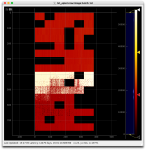
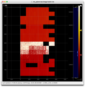
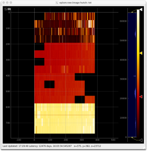
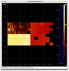
As of April 1, 2024, another detector (0016778240-0176075265-0452984854-4021594881-1962934296-0177446913-0402653206) is being readied for an upcoming beam test. With the delays provided by the detector-specific .yml file and the automatic bad lane disablment done by the Root class on Configure, the third and (later) fourth images above were obtained.
Running the DAQ
The beam-test ePixM is currently in the FEE test stand. To run it, log in to drp-neh-ctl002. You can use your own account or detopr (if you can make it work), but avoid rixopr for now. Change directory to where you want to work and execute the following:
ln -s ~rixopr/git/lcl2_040324/setup_env.sh
cp  ~rixopr/git/lcl2_040324/psdaq/psdaq/cnf/epixM.cnf .
You can modify the .cnf copy as you see fit. Prior to running the DAQ, source the setup_env file. Run the DAQ with procmgr start epixM.cnf. See the Beam Test Trigger Setup section of the EpixHR page for setting up the trigger. There are a set of scan scripts available which can be run as:
python ~rixopr/git/lcls2_040324/psdaq/psdaq/cas/epixhr_timing_scan.py -p 3 -C drp-neh-ctl002 --hutch tst --config BEAM --detname epixm_0 --scantype timing --events 2000 --record 1
python ~rixopr/git/lcls2_040324/psdaq/psdaq/cas/epixm_pedestal_scan.py -p 3 -C drp-neh-ctl002 --hutch tst --config BEAM --detname epixm_0 --scantype pedestal --events 2000 --record 1
python ~rixopr/git/lcls2_040324/psdaq/psdaq/cas/epixm_chargeinj_scan.py -p 3 -C drp-neh-ctl002 --hutch tst --config BEAM --detname epixm_0 --scantype chargeinj --events 2000 --record 1
Move the DAQ in the ALLOCATED or CONNECTED state prior to executing one of them.
The location where the data is recorded is governed by the .cnf file. With epixM.cnf as originally provided, this is the Lustre filesystem at /drpneh/data. This path is accessible only from drp-neh-cmp0XX nodes. The full path of the data files can be found in the log files.
Details
Run the DAQ as follows:
ssh drp-neh-ctl002
cd scripts
. ./setup_env.sh
procmgr start epixM.cnf
A bunch of windows will come up after the procmgr start command is given. Usually the first thing to do is to click the Select button in the Partition area of the DAQ Control GUI. It may take a few moments before the Select partition window pops up (called Rollcall), depending on previous history and the state of the system. Once the window appears, select the detectors you want to include in your run. The detectors will by default be assigned to the readout group (grp) for the platform on which you launched the DAQ (nominally 2). Under some circumstances, this must be changed, but can be left alone for now. Optionally select ami-meb0 if you plan to use AMI. It should look like the first screen-shot below:
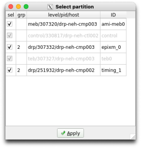
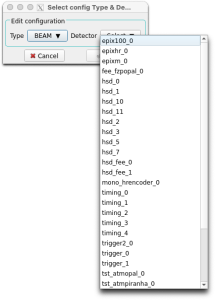
From this you can see that the ePixM detector is named epixm_0 and runs on drp-neh-cmp003 (in the FEE test-stand). The timing DRP is named timing_1 and runs on drp-neh-cmp002. These names are set up in the .cnf file. Note that changing them also requires corresponding changes to the configuration database (configDb). To access and modify an entry, click on the Edit button in the Configuration section of the Control GUI. Leave the Type at BEAM and use the Select pull-down to choose a detector. You'll see the two detector names currently in this DAQ instance in the configDb list, similar to the second screen-shot above.
You may find you need to modify the epixm_0 and/or timing_1 database instances to adjust various parameters. As an example, below is a screen-shot of the epixm_0 configDb instance, highlighting the run_trigger_group parameter. You might want to change its value if it conflicts with another detector's or DAQ's usage.
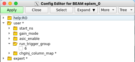
In the expert section, parameters can be found with which to initialize the ePixM device's registers. The configDb has been initialized with data from the .yml files supplied with the epix-hr-m-320k project. It is organized in a way similar to what one sees with the device's devGui.
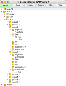
In the timing_1 configDb section, one can find the parameters for setting up the trigger. Take care to modify only the groups appearing in the Select partition pop-up (above) to avoid interfering with other DAQ instances. As an example, the second screen-shot above shows that group 2 has been set up to trigger at a fixed rate if 10 Hz, and group3 has been set up to trigger on eventcode 261.
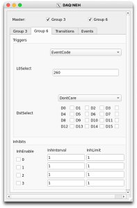
Sometimes a group is used implicitly, as with the ePixM's (and ePixHR's) Run Trigger group. Its parameters are not governed by the configDb instance, but instead are manipulated directly using the groupca GUI and a script. The Beam Test Trigger Setup section of the EpixHR page describes one such script and how to run it. With groupca, one then enters values on the appropriate group tab to set up rates, event codes, etc., as shown in the first screen-shot below:
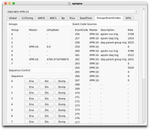
Note that which tabs groupca displays is governed by the launch line for it in the .cnf file. On the Groups/EventCodes tab of the xpmpva GUI (second screen-shot above), one can see what event codes already exist and what their parameters are. Once the settings are dialed in, switch to groupca's Events tab to verify that the Run Trigger's group is running (L0InpRate not equal to 0). If it isn't running, click the Run checkbox to start it. Unfortunately, this will also start the other group (DAQ Trigger), which may confuse the DAQ. To recover, either restart the DAQ with:
procmgr restart epixM.cnf
or move the Target State in the Control GUI to RESET. Then Apply the detector selection again.
The Control GUI is built around a Finite State Machine. The configDb values are applied to the hardware when the DAQ goes through the Configure transition. Remember to re-Configure (unwind the state machine to CONNECTED or below) when you make a change.
Once the parameters have been set up as desired, a run can be taken. Decide whether you want to run with or without recording and click the Record button on the Control GUI, as appropriate (must be done when the state machine is in a state lower than BeginRun). Then move the Target State to RUNNING to start the run. When done, move the Target State to PAUSED (or lower, e.g., CONFIGURED) to stop the run.
Alternatively, there are scripts with which to run a scan. Available scans are timing, pedestal and charge injection. These can be run by first putting the DAQ in the ALLOCATED state (procmgr start followed by Applying the detectors chosen in the Select partition pop-up) and running one of the following scripts:
python ~rixopr/git/lcls2_040324/psdaq/psdaq/cas/epixhr_timing_scan.py -p 3 -C drp-neh-ctl002 --hutch tst --config BEAM --detname epixm_0 --scantype timing --events 2000 --record 1
python ~rixopr/git/lcls2_040324/psdaq/psdaq/cas/epixm_pedestal_scan.py -p 3 -C drp-neh-ctl002 --hutch tst --config BEAM --detname epixm_0 --scantype pedestal --events 2000 --record 1
python ~rixopr/git/lcls2_040324/psdaq/psdaq/cas/epixm_chargeinj_scan.py -p 3 -C drp-neh-ctl002 --hutch tst --config BEAM --detname epixm_0 --scantype chargeinj --events 2000 --record 1
See the -h option of these scripts for usage information. Note that the timing scan can be done with the ePixHR script while the pedestal and charge injection scripts are specific to the ePixM.
When you're done with the DAQ, it can be closed down with:
procmgr stop epixM.cnf
Overview
Content Tools