Overview
Our first large area detector (2Mpx, 5kHz). Total data volume 2Mpx*5kHz*2bytes/px=20GB/s. 5 tiles in each quad. Each tile is 4 asics. Each ASICs is 144*192*4 (4 is number of asics).

Issues
Possible fiber configurations (with uniform distribution of tiles across nodes):
- 4 nodes: 5 tiles (1 quad) per node (5GB/s on one node, 21Hz per core (full-image equivalent))
- 10 nodes: 2 tiles per node (2GB/s on one node, 8Hz per core(full-image equivalent))
- 20 nodes: 1 tile per node (1GB/s on one node, 4Hz per core(full-image equivalent))
Is a segment a tile? or a set of tiles (e.g. 2 or 3)?
Two ideas: segments, and "unit cell". Should those ideas be identical?
Would make my brain hurt the least if we made a tile a segment (that's been our previous approach). Also allows us to change the fiber configuration as time goes on without defining a new segment type.
Perhaps we should mock-up the epixhr segment idea in advance using the kcuSim detector?
The configuration is only done on one node. But we can make sure that the configuration object is present on all the relevant nodes (and in the associated xtc file).
Another concern is the node that has the 6 KCU cards for the multimode to single mode conversion of 48 fiber pairs (perhaps minus 4 since in principle the timing can be sent with the local txi xpm using multimode?).
Do we also need to support det.image in the DRP?
Multimode to singlemode conversion:
- Need to buy a big node (like hsd node) to hold 6 kcu cards
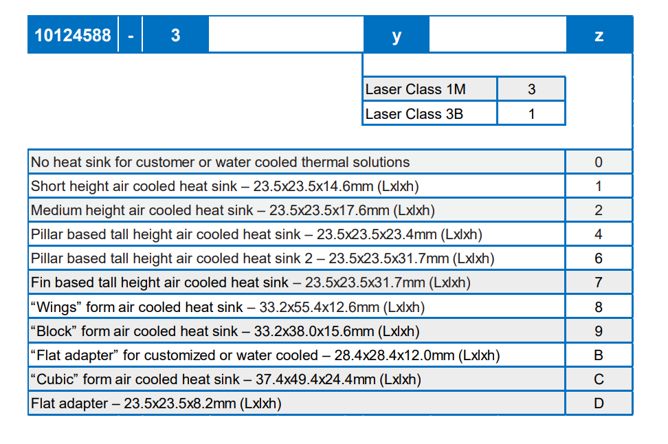
- dionisio says this mtp24 is only available in multimode: https://www.mouser.com/ProductDetail/Amphenol-FSI/10124588-310?qs=81r%252BiQLm7BSk9m%252B2puhj7Q%3D%3D.
- see also https://www.amphenol-cs.com/product-series/leap-on-board-transceiver.html
- see also https://www.amphenol-cs.com/optics/transceivers.html
- amphenol tells us to contact our local sales rep: Gaurav.Singh@amphenol-fci.com
- feedthroughs may also be a problem. Kaz is getting part number RETA-RIB-CF40-24-GI50-025-S70-MTPF (24 fibers) and RETA-RIB-CF16-12-GI50-025-S48-MTPF (12 fibers) from sedi-ati.com. These two parts are similar to RETA-STANF21.208 (different length) and RETA-LBNL19.141 (different flange). Looks like feedthroughs are available in single-mode!
- transceiver outputs MPO24 (12 fiber pairs). the vacuum feedthroughs will also be MPO24
- timing comes from XPM. configuration/monitoring/data fibers connect to DRP. we will use LC plus cassettes to get to MPO24 (and MPO8 going to the multimode to single mode converters).
- need to have/order:
- a node to hold all the multimode-to-single-mode converter KCUs
- LC to MPO24 cassettes
- MPO8 breakout cables
Amphenol says these are "variants" of the transceiver that they support:
SZ Compression
Chuck writes about roibinsz:
# Convert to ms/image/core
Given 4M pixels x float32 (4 bytes) = 32 MB/image,
89.89GB/32MB => 2809 images/s on 400 cores => 7 images/s/core => 142ms/image/core
For a 2M detector, this would take half the time => 71ms/image/core
This 71ms number + 20ms for calibration feels tight on 10 nodes. Implies 10Hz per core, or 500 cores (8 nodes)
This paper compares CPU/GPU SZ compression: https://arxiv.org/abs/2007.09625. It states 370x improvement on GPU vs 1 CPU core. If we have 60 usable cores on a DRP node, that makes a GPU-SZ node the equivalent of 6x faster than a CPU-SZ node.
Schedule
(on Dec. 19, 2022) Sometime in February/March a prototype with 3 tiles will be released (could generate fake data for missing panels for 1 quad). Full detector: summer?
Calibration Time
Running this script on a psffb node (twice so we get all the data in cache so it behaves more like the daq). Do we also need to support det.image in the drp?
import time
from psana import *
ds = DataSource('exp=mfxx1005021:run=340')
det = Detector('epix10k2M')
for nevt,evt in enumerate(ds.events()):
    calib = det.calib(evt,cmpars=[0,0,0,0]) # disable common-mode with cmpars
    if nevt>=20: break
    if nevt==0: tstart=time.time() # start the timer after first event (which is slow)
print('time per evt:',(time.time()-tstart)/nevt,'nevt:',nevt)

(ana-4.0.48-py3) drp-srcf-eb004:lcls2$ python ~/junk.py
time per evt: 0.019545722007751464 nevt: 20
(ana-4.0.48-py3) drp-srcf-eb004:lcls2$ python ~/junk.py
time per evt: 0.019071054458618165 nevt: 20
So 20ms/core, corresponding to ~50Hz. For the record, with common mode (the default) the det.calib time increases to ~140ms, and det.image is ~170ms. That implies for 5kHz we need 100 cores, or ~2 nodes. Hopefully we don't need common-mode in the DRP. The algorithms Mikhail runs are listed here: Method det.calib algorithms#Detectordependentalgorithms
Comparing to a simple C++ calibration algorithm:
#include <stdint.h>
#include <stdio.h>
#include <string.h>

#define RAW_SIZE 2000000
#define NIMG 200
uint16_t raw[NIMG][RAW_SIZE];
float result[RAW_SIZE];
uint16_t peds[RAW_SIZE];
uint8_t mask[RAW_SIZE];
float gains[7][RAW_SIZE];

int main() {
    memset(mask,0,RAW_SIZE);

    for (unsigned count=0; count<NIMG; count++) {
        for (unsigned i=0; i<RAW_SIZE; i++) {
            unsigned val = raw[count][i];
            unsigned range = val&0x7000;
            result[i] = mask[i] ? 0 : ((val&0xfff)-peds[i])*gains[range][i];
        }
    }
}
With this we see about 7ms per image:
(ana-4.0.48-py3) drp-srcf-eb004:lcls2$ g++ -o junk junk.cc
(ana-4.0.48-py3) drp-srcf-eb004:lcls2$ time ./junk

real	0m1.432s
user	0m1.423s
sys	0m0.006s
Fiber Connections
A slack conversation with Dionisio and Matt:
Hi Dionisio, I believe TXI is getting an epixhr 2Mpx and we have to purchase daq equipment for it now.. Can you tell me how many fibers that detector will have? Thanks!
That detector will use the 12 lane transceiver
and there will be 4 fiber bundles per 2M camera
one fiber per quad similar to the analog 10k camera
I assume you mean “one fiber bundle per quad” above? And 12 fibers per bundle, so a total of 48?
exactly
Sorry, one more question: each fiber will be 6Gbps or something higher?
48 fiber pairs, I assume.
all lanes are bi-dir
so yes, 48 pairs
6gbps?
these are the fibers I am planning to use here for testing
We need single-mode.
Those look like multi-mode.
these are the fibers that can connect to the transceiver. MM to SM conversion will be needed for this camera and we need to plan of which option we will use for that (same as it was done for ePix HR? or something else)
Perhaps we discussed before and I forgot. Doing the MM to SM conversion for 96 fibers feels unsustainable.
We discussed before. The transceiver on the detector end only exists for mm now.
Do I understand correctly we would need 48/8=6 kcu cards to to convert all of them? That will require a larger node.
I’m also worried because I had significant problems with lane-locking with the converter-card for the epix100. I had to mix-and-match lanes to find one that locked. Optical powers looked good. If we really need to do this conversion we should probably use that converter card to understand the lane locking problems. Maybe I needed to clean all the fibers somehow, even though the optical powers looked good?
Fiber Lane Assignments
Preliminary, from Dionisio
Lane[0].VC[0] = Data[0]
Lane[1].VC[0] = Data[1]
Lane[2].VC[0] = Data[2]
Lane[3].VC[0] = Data[3]
Lane[4].VC[0] = Data[4]
Lane[5].VC[0] = SRPv3
Lane[5].VC[1] = XVC
Lane[6].VC[3:0] = slow monitoring[3:0]
Lane[7].VC[3:0] = o-scope[3:0]
Lane[10:8] = Reserved for edgeML
Lane[11] = LCLS-II Timing

Can split the fibers onto different nodes.
Data is not currently in a natural order in the fiber, but plan on doing this in the tile electronics.
Calibration Issues Related to Data Reduction
Focusing on SAXS/WAXS in TXI for now, needed for data-reduction techniques: angular integration, cube, libpressio/libsz.
- offsets (use phil's max/min technique) run offline (at least at the start) perhaps on prescale events
- ideally needs work (automation)
- pedestals (dark)
- gains (use charge injection or flat fields or design numbers)
- bad pixels
- used dark runs for this in the past, but Mikhail is adding a new set of calibration constants so that other data (e.g. flat-field) can contribute to bad pixel masks
- geometry:
- beam center (use silke's canny)
- needs some work, e.g. integrating with LCLS2, fit-stability (e.g. with blobby rings)
- Cong also has software for fitting silver-behenate rings (using LCLS1 data)
- panel positions (epixHR2M on movable jaws).
- needs work
- not a flat detector
- mikhail has software that projects onto a plane (will have to project the result back
- do we have 3D metrology measurements for this detector? phil thinks yes. should check with chris kenney. ideally would have metrology as a function of jaw separation.
- we think TXI will have fuzzy silver behenate rings (ask Andy about this)
- Chuck can tell us about LCLS1 silver behenate data
- could we use motor positions for the panel positions? didn't really
- beam center (use silke's canny)
- timetool+delaystage
- delaystage is relatively easy (e.g. gets changed in a step scan)
- either a mechanical stage (uses speed of light) or an electronic delay stage which are also well understood
- for the timetool camera edge-finding, want to convert the edge-position to picoseconds
- this has been done routinely at XPP but not automated way
- harder in XPP than CXI because you have to filter out bad events
- filtered events: bad camera edge-fits, or width of the edge is too large, or amplitude of the edge, or the pulse-energy of the beam
- ideally we would have a psana detector with calibration constants
- the calibration constants exist for the opal. Ric has done some work porting the opal code to the piranha, but not complete.
- needs work testing the calibration procedure and piranha edge-finding
- delaystage is relatively easy (e.g. gets changed in a step scan)
Overview
Content Tools