Schedule
| Day/Week | Date | Activities | Program | |
|---|---|---|---|---|
| Thursday-Saturday | Dec/6-8 | T577 stand alone running. Day shift AMO beam unusable. | ||
| Sunday | Dec/9 | T577 running at 5 GeV | ||
| Monday | Dec/10 | Day: T577 changing energy to 8 GeV. | Night: T539 at 8 GeV | |
| Tuesday | Dec/11 | Day: T577 running at 8 GeV. | Night: T539 at 8 GeV | |
| Wednesday | Dec/12 | Day: T577 changing to 3 GeV until beam off 1pm | ||
| Thursday | Dec/13 | Day: T578 (UCSC/HGTD) setup | Night: T539 at 12.6 GeV | |
| Friday | Dec/14 | Day: MD, no beam. HGTD setup continues | Night: T539 at 12.6 GeV | |
| Saturday | Dec/15 | T578 HGTD runs start | ||
Main Goal
The Nov/2018 T539+T545 session had reduced beam time due to one primary LCLS experiment didn't permit the 5 Hz parasitic beam to ESTB. A makeup shared session was negotiated during this period with T577 (Moller calorimeter) also using secondary beam. The main goals of this test session:
1) Collecting similar data as November session for the two SLAC RD53A modules with different active silicon thicknesses from the two LBNL modules. These modules didn't get beam time in November due to truncated session.
2) An independent examination of the L1A time distribution with the SLAC HSIO2+FEB readout. Data taken so far with YARR all exhibited a very broad distribution.
Preparation
Caladium was moved into place at the start of T577 and remote driven to far wall with 1-2 inch clearance from beam line so that we can remote drive it back to beam line.
A97 had 1000e tuning from Timon on YARR during last period. Checked with RCE+FEB calibration looking OK
| A97 | Thresholds | Noise map | |
|---|---|---|---|
| YARR | 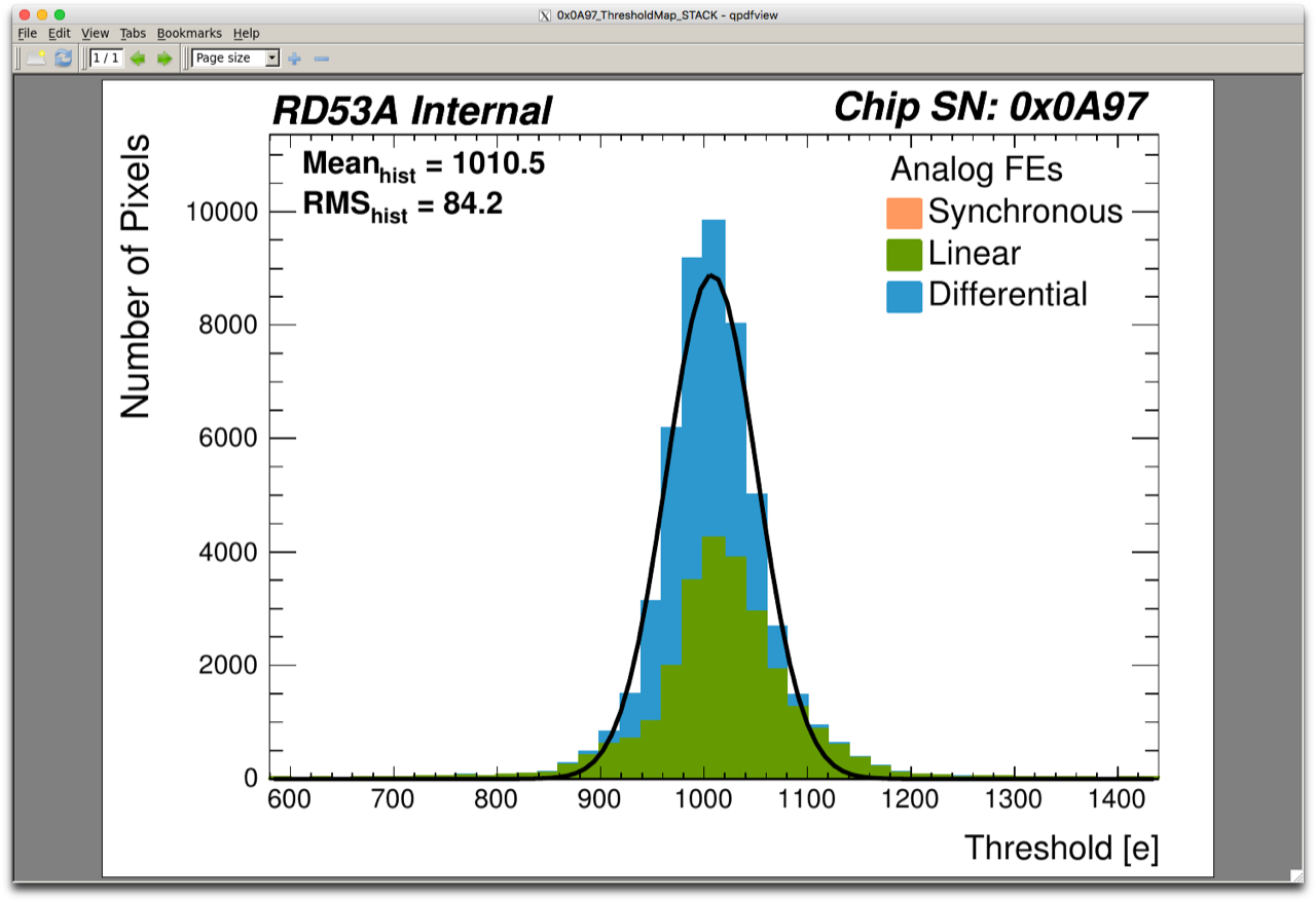 | 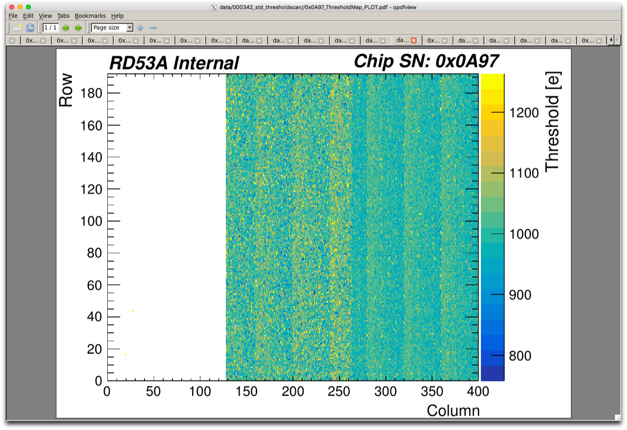 | |
| HSIO2+FEB |
B53 had brief tests by Aleksandra before sent to SLAC
| B53 | Thresholds | Noise map |
|---|---|---|
| YARR | 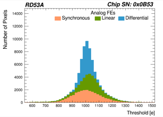 | 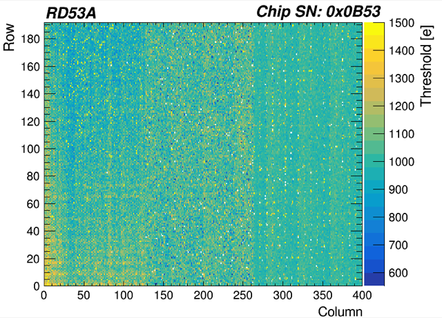 |
| HSIO2+FEB |
Installation Inventory
- RD53A module on DUT mounting frame
- FEB board + 12V supply
- HSIO2 (C02) with 12V supply
- FEB-HSIO2 QSFP->LS fiber
- DisplayPort cable
- Agilent LV supply with GPIB controller, LV cable to FEB. Ethernet cable to Fanless box.
- Keithley HV
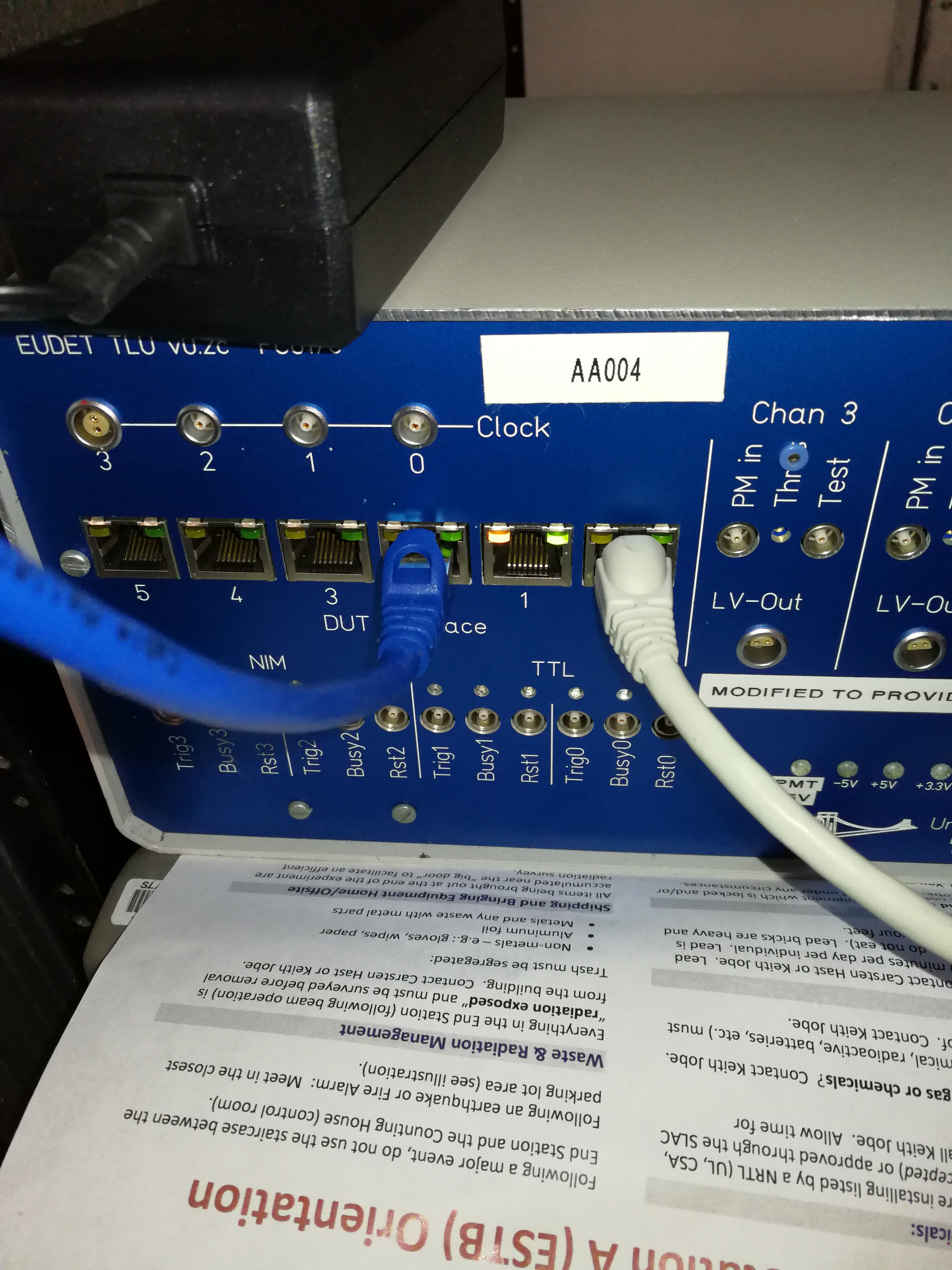
- TLU box with its voltage supply + square USB link to Fanless box
- Additional NIM discriminator from ESA for better trigger fanout cleanup + LEMO cables
- Tie-wrap mounting for FEB
Dec/10 Night shift
Zijun, Ke, SD
9:30pm T577 wrapping up last scan. Since we would like to go to ~100e/pulse for tuning first, T577 decided to turn off and moved out of beamline.
9:45pm Access to install. New setup needs HSIO2 DTM to be connected to the ESA-RESTRICTED network to run YARRproducer on it. The network switch ports are completely full ! Fanless box esadutdaq1 was taken out of the network with it ethernet cable on Belden Ch-8 disconnected. Took a while to find Belden ch-11 was not connected to anything so disconnected it and used its switch port for ch-8 to bring back Fanless box. DTM IP is set to the 104.52 as the YARR DAQ node used to be. The gateway and netmask also needs to be exactly right to appear properly in the network:
HSIO2 DTM | 172.27.104.52 |
|---|---|
| Gateway | 172.27.104.1 |
| Netmask | 255.255.252.0 |
Trigger channel problem: while Trigger ch-11 (HGTD) has a healthy TTL signal as usual, our regular Caladium Trigger ch-10 (NIM) appeared to be totally dead. Sending TRG11 to a TTL->NIM converter didn't get any NIM output and eventually realized that the NIM<->TTL converter is a bad module. Grabbed another NIM<->TTL from ESA upstairs and this finally worked. We are not driving the TLU trigger from TRG11 after TTL->NIM.
4:45am Asked for beam but MCC couldn't get it going - cooling water for kicker magnet too cold ! MCC tried several times with no success.
10:30am Still cannot turn on magnet. Give up. Moved Caladium out of beam line for T577 to take over day shift.
Dec/11 Night shift
Zijun, Ke, SD
9:00pm T577 needs another 2 hours to wrap up this round of tests until 11pm. Tonee found space heater for the kicker magnet so hopefully access is no longer as ,much of a risk, but we still need to avoid long access.
10:30pm Running parasitically outside beam. YARRproducer is strobing with beam trigger correctly building events. Also saw some noise hits in the data (yesterday's tests had no hits at all which sounded a bit suspicious but could be noise just very low still).
00:00 T577 done for the night. Moved in Caladium for beam with RD53A A97 as DUT at 0 degree angle (perpendicular), and mounted with RD53A X = Calladium X.
00:30 Talk to operator to get higher particle rate for latency scan. Open up slit had rather little effect in brining update but opening up collimator had more desired change to increase the beam spot from 2x2mm to covering about half of MIMOSA plane, and 80 pixel hits/MIMOSA (~40 particles).
00:35 LCLS primary experiment wants to change primary beam energy. Beam off temporarily, but will return for same 8 GeV secondary setup for ESTB.
00:55 Beam back. Beam spot as tuned and ~40 particles per pulse. Using this to scan latency.
0:55 Trigger 11 starting panel delay setting is -104500. Our RD53A DAQ window is 32 beam crossings = 800nsand a configured latency of 64. Stepping towards large delays (more -ve numbers) by 500ns steps. Didn't find it in this direction. Went the other way. Found it at trigger delay = -102010 which will put most data at tick=8.
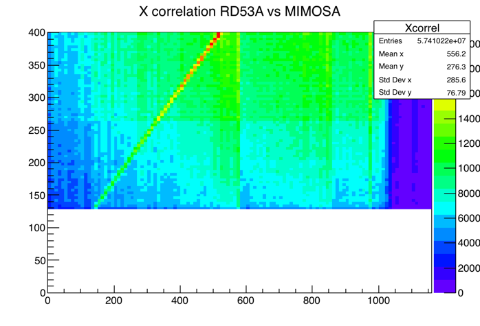
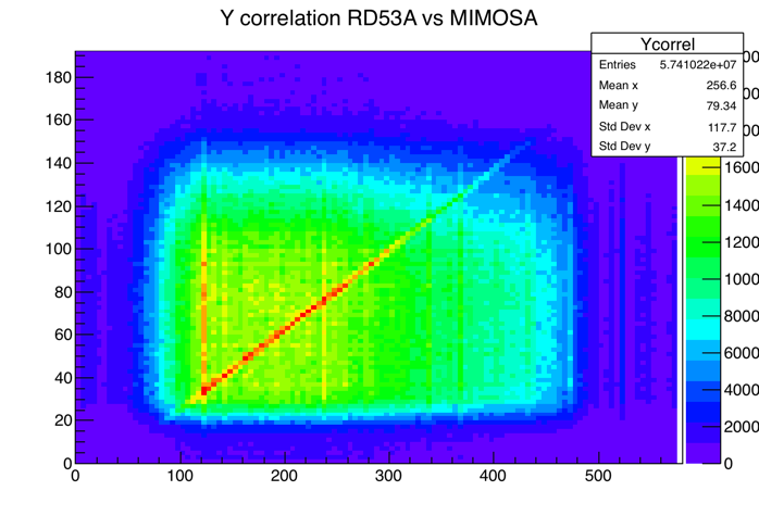
1:45 Fine tuned RD53A DUT position Y+4mm, X+6mm to center the spot onto RD53a module. Saved histogram for Run 652. Cannot see MIMOSA vs RD53a correlation yet.
1:50 Started Run 653 with beamspot centered as high stat local RD53a hit analysis sample.
| Run | Start | End | Event | Particle rate | Tilt | Comments |
|---|---|---|---|---|---|---|
| 653 | 1:50 | 2:05 | 4852 | 40 | 0 | Ended to try new version of producer |
| 683 | 3:22 | 3:55 | 9906 | 40 | 0 | (eventNumber offset -1, new version of YarrProd still can not sync with MIMOSA) |
| 684 | 4:00 | 4:34 | 9908 | 40 | 0 | ((eventNumber offset 0, new version of YarrProd still can not sync with MIMOSA) |
| 686 | 4:49 | 5:20 | 9908 | 40 | 60 | (x increase 5 mm) |
| 687 | 5:23 | 5:56 | 9928 | 40 | 60 | same running condition as 686. Suddenly found YarrProd sync with MIMOSA, so, maybe run 684 and 686 also sync. |
| 688 | 5:58 | 6:05 | 2338 | 40 | 60 | (Not sync, so, looks like 687 just accidently sync) |
 |  |  |
|---|---|---|
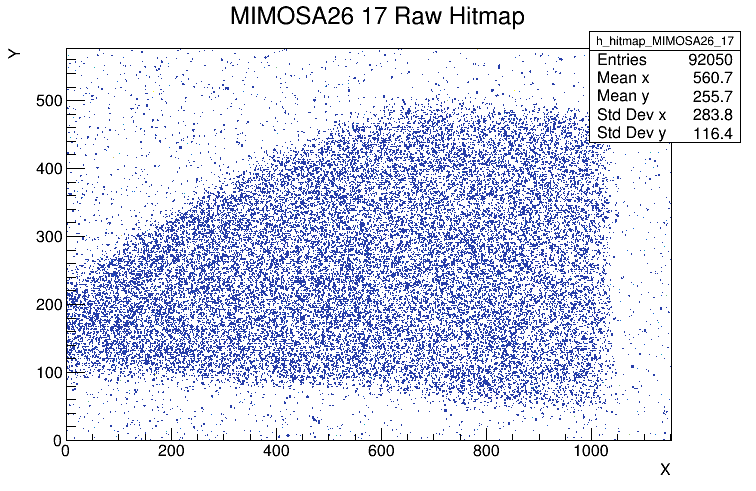
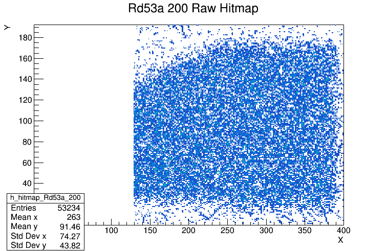
| Run 684 beam spot from 3rd MIMOSA plane | Run 684 RD53A (A97) hit map | |
 |  | |
 |  |
 |  |
|---|---|
| Dec/11 11:54pm. Applies to Run 653-684. Beam L->R. | Tilt just before Run 686-688. Beam R->L. |
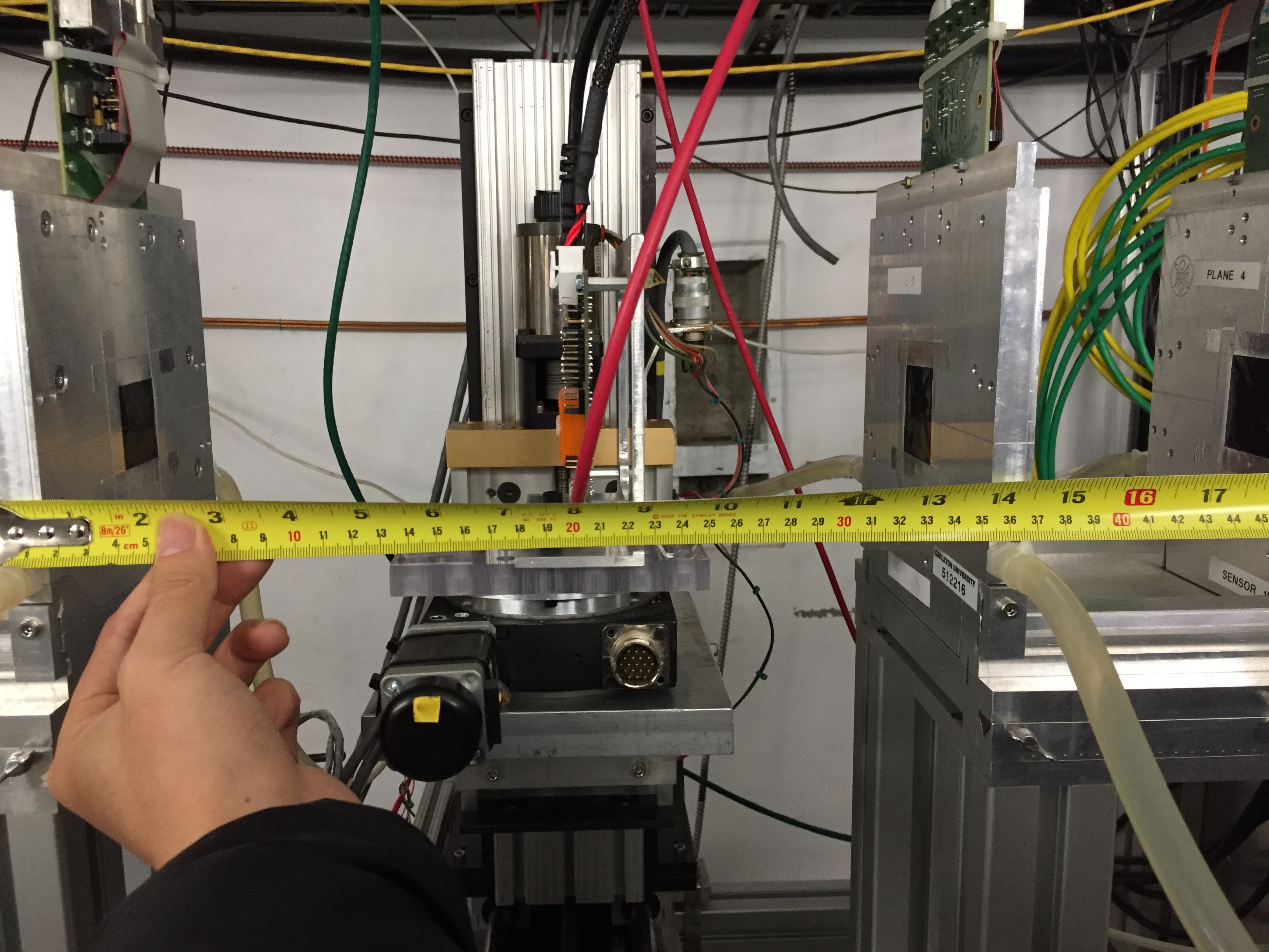
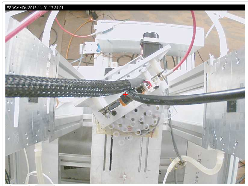
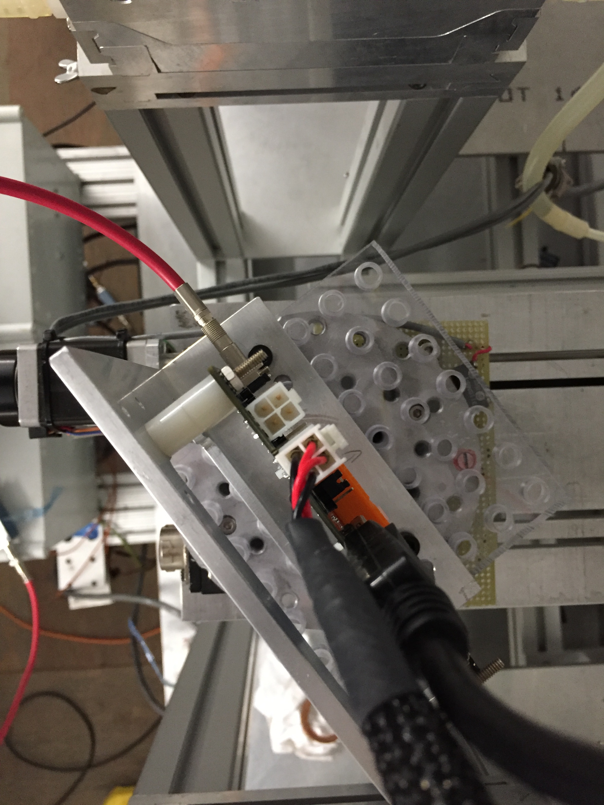
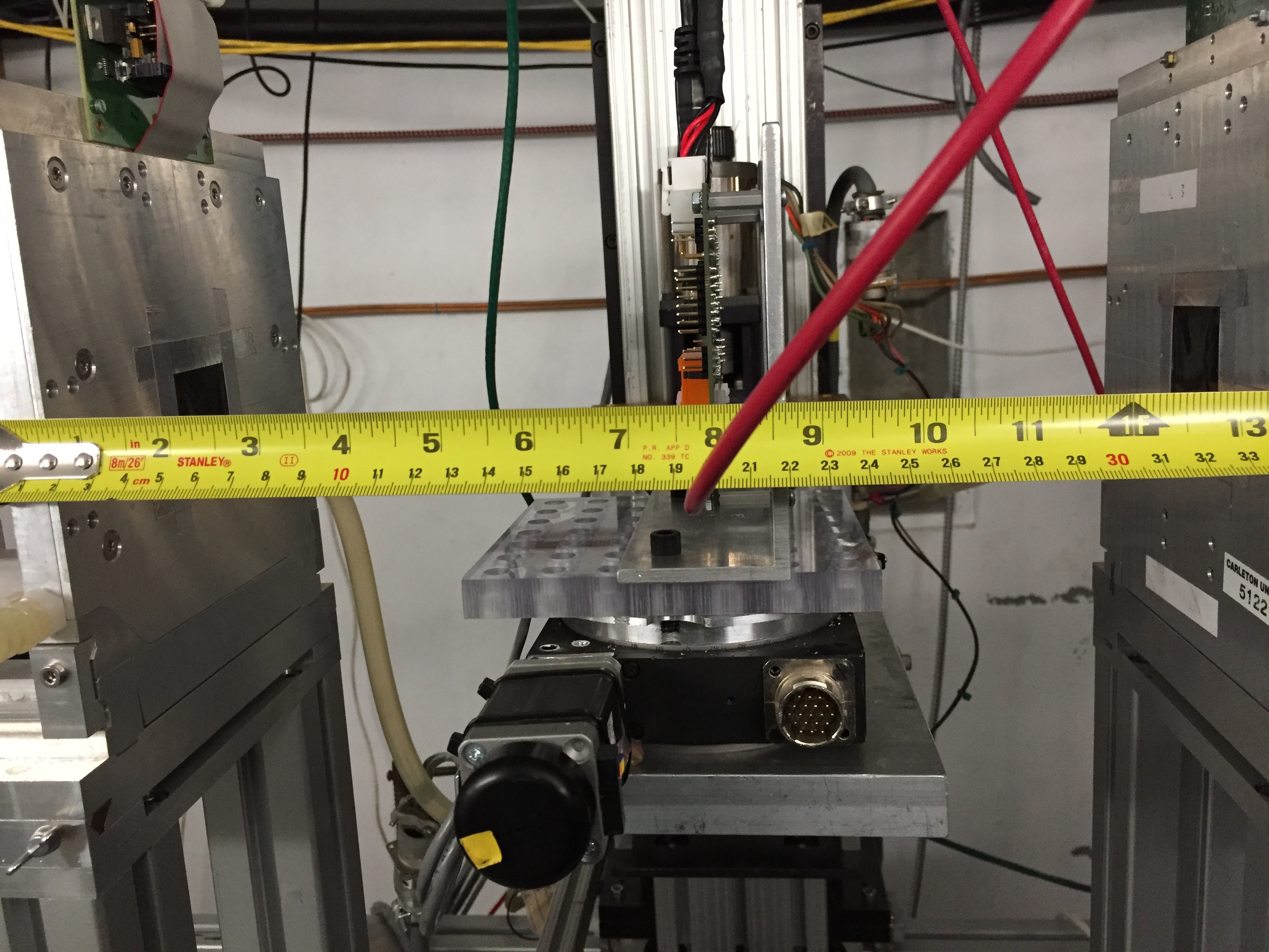
MIMOSA and DUT positions: Caladium was measured in Jan/2016 session as documented in the Jan/2016 commissioning session Twiki which should be still correct for the plane separate of 152mm between the 3 front planes, and between the 3 back planes. However, the DUT gap looks like was increased to 357mm from the original 307mm, probably when we tried to insert the dry ice foam box for irradiated DUTs. We typically measure the DUT gap with tape header clipped to the front face of the 3rd EUDET plane as shown above. In this tape coordinate, the 3rd MIMOSA plane is at z=2.65mm behind the EUDET support metal front face (see EUDET hardware wiki). RD53A DUT (right edge of orange box) looks like to be at z~204mm which would imply the RD53A plane is at ~201.5mm behind the 3rd EUDET plane. When tilting with remote DUT rotation, the XZ transformation is unfortunate dependent on the mounting of the DUT and the rotation is not centered around DUT device so that it changes the mean z coordinate and also needs a DUT x shift to bring back to the beamline.
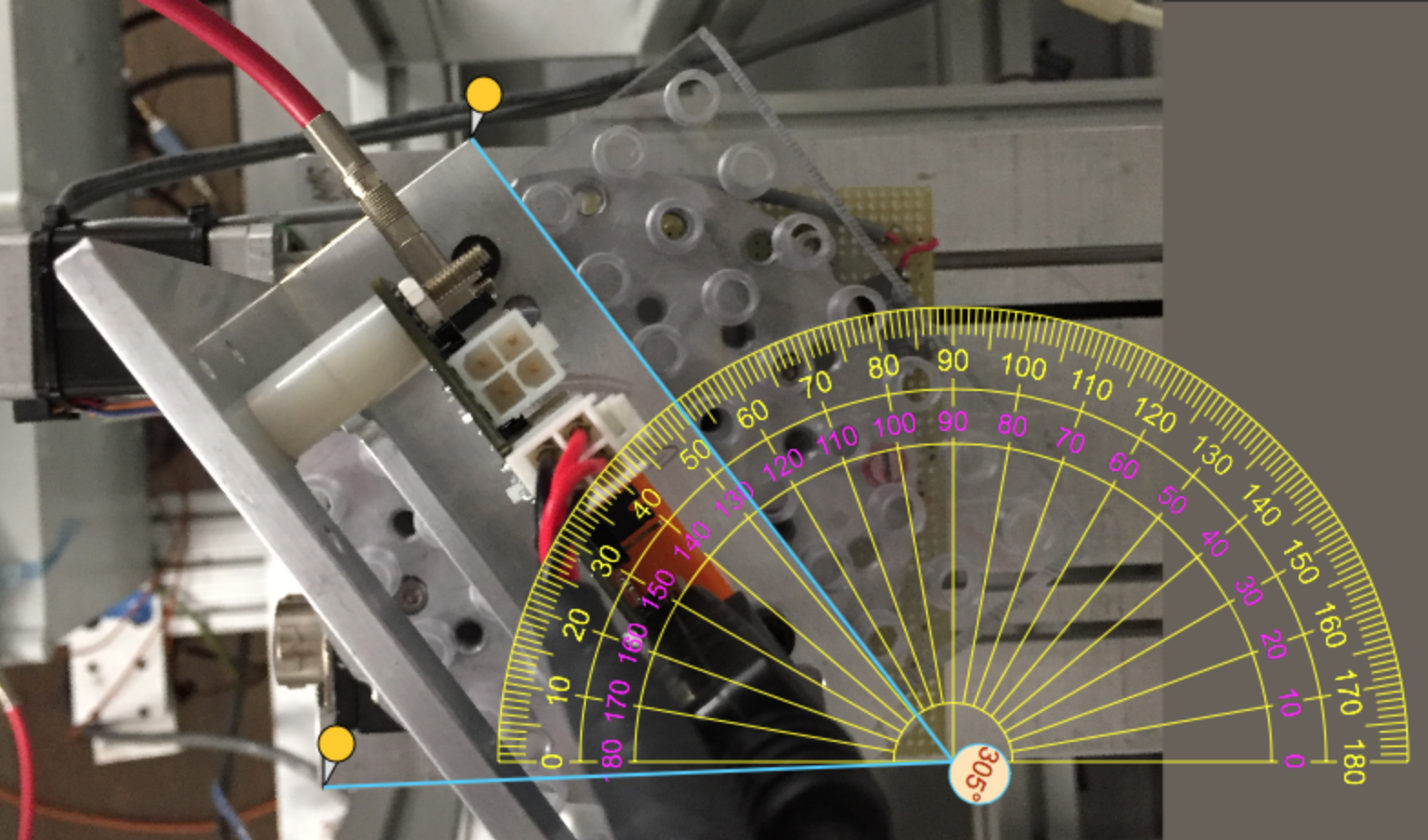
Plots from tilted Run 686:
 |  | |
|---|---|---|
 |  |
7:40 stop testing A97, replace with B53.
7:59 starting with the Tuned chip config file from LBNL for beamtest. B53 hase tens of very hot pixel. Need to mask the hot pixel.
~8:20, shut down beam to run quick digital/analog/thresold scan. The analoy scan pick out all the hot pixel and automaticly mask them out.
8:54, beam test with the new config file, looks like most of noisy pixel are quiet now.
| Run | Start | End | Event | Particle rate | Tilt | Comments |
|---|---|---|---|---|---|---|
| 714 | 8:54 | 9:02 | 2107 | 35 | 0 | noise pixel masked, stopped because of beam change |
9:03 beam change, so no beam for ESA. Beam is expected to be back after ~15mins
stop at 9:24.
Dec/13 Night shift
Zijun, SD
T578 HGTD period starts today but they are not ready to run until Saturday. Some additional time for ITk at the mean time.
Surrendered the HSIO2 Ethernet cable (Belden ch 8) to HGTD setup and the ESA-RESTRICTED network ports on the ESA switch 25-48 is completely jammed full. Took a long time to find Belden ch 24 is for power strip on an unused rack just outside the ESTB tunnel mouth. Displaced that cable at Ch 24 with Ch 11 cable connected to HSIO2 to bring that back int the network.
Night shift got Howard to produce a new setup to derive a 12.65 GV secondary beam for the 14.65 GeV primary beam. It looks like this set can work with the remaining night shifts of this period, but Day shifts with MEC starting Saturday is 10 GeV primary beam which needs a separate setup to run 8 GeV secondary. The tuning of the 12.65 secondary beam had a few surprises with momentum cuts moving spot location etc. We settled with a round beam spot covering ~1/3 of the MIMOSA at ~70 particles/pulse. The beam spot is shift by a few mm in -X and -Y which needed to move whole Caladium to recenter.
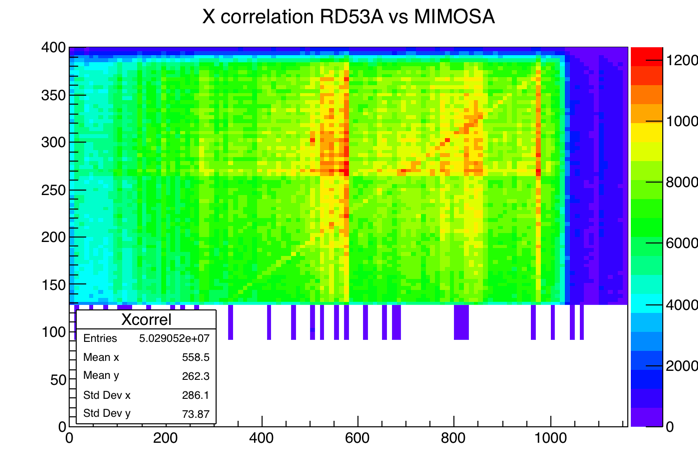
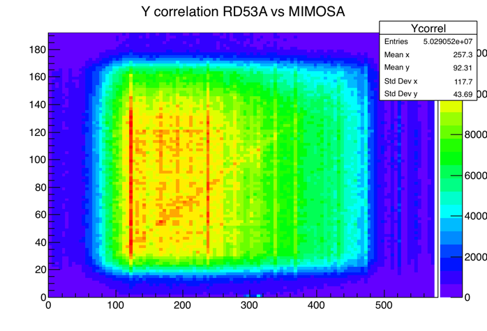
Whole shift of test runs debugging the loss of event ID match between Caladium and RD53A readout. Some runs got good MIMOSA vs RD53A X,Y correlation at start at least and other runs were not aligned. There were some odd extra event looking like real distinctive RD53A beam hit data at DUT readout but never found a matching MIMOSA event data. TLU ch-1 RJ45 port is somewhat suspicious and sometimes could not communicate with FEB. Moved FEB link to TLU ch 2. More stable communication to FEB, but the issue of extra event on RD53A side remains.
Dec/14 Night shift
Day shift: UCSC T788 setup continues during MD. One main issue to resolve is the dead Trg-10 for Caladium. T578 needs both Trg-10 (NIM for Caladium) and Trg-11 (TTL for HGTD). Didn't manage with connect with Doug to debug the dead Trg-10, but he passed on a schematic for the ESTB trigged patch scheme:
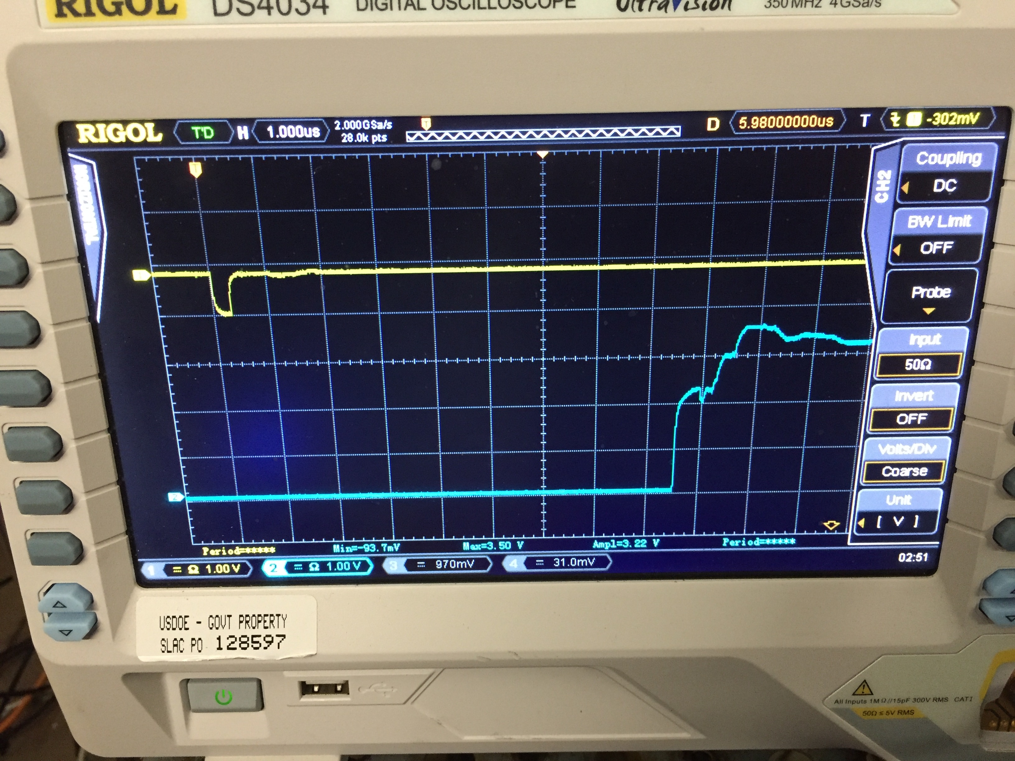
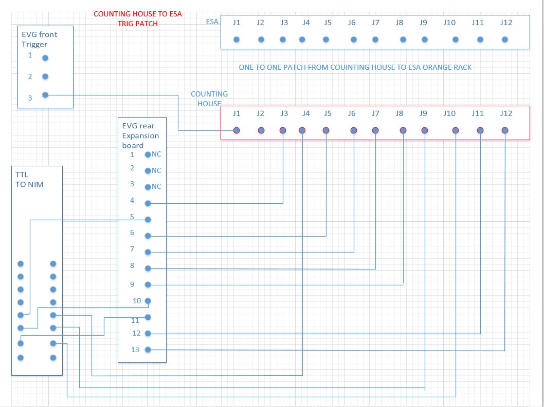 | 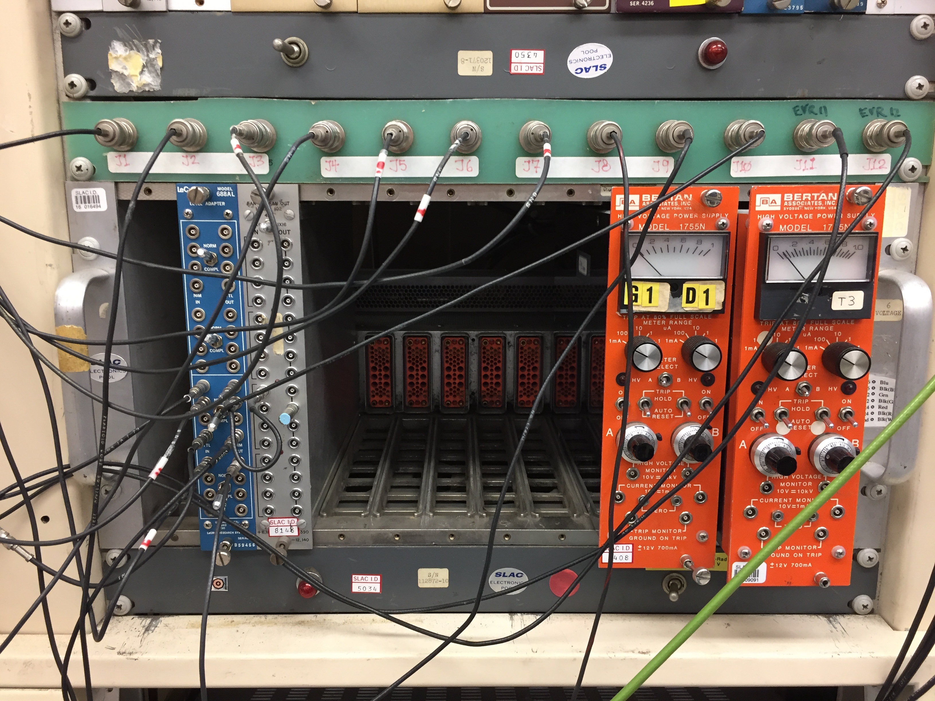 | |
|---|---|---|
| Counting house patch panel. Note the very taught LEMO cable leading to J10. | Yellow=Trg-10 (NIM); Cyan=Trg-11 (TTL) at Caladium rack. The 8.5us delay between them seems to commensurate with the delay panel settings: (-102010) - (-110488) = 8478 |
The issue with Trg-10 is not obvious: EVG rear expansion board ch 11 (LVTTL?) is one of the inputs (the other input is EVG Front trigger 2) to the Lecroy level adaptor in compl mode tuning that into a 1.2V and 300ns width NIM. The only part looking suspicious is the LEMO cable taking the NIM output to J10 looks very tight. Replaced that part with a slightly longer cable. This did effectively bring the Trg10 NIM signal back to Caladium rack but signal shape weak. Decided to connect J10 directly to EVG rear 11 to send TTL signal over long path to tunenel and used TTL->NIM at caladium rack for a much more solid NIM signal to TLU.
Night shift: ZiJun,SD
Finally, realized that TLU RJ45 ch1 defect is one of the reasons for events synchronization failure between MIMOSA and RD53a.
1) FEB can not get trig signal from TLU ch1;
2) MIMOSA can receive trigger signal from TLU ch1, but the TLU words from TLU ch1 are wrong. Left plot is the TLU words distribution from ch1, while right plot is the TLU words from ch0.


Now, connect TLU ch0 to MIMOSA, and ch2 to FEB.
5:26 am New version of YARRproducer stabilized the synchronization between MIMOSA and RD53a readout. Previous version used local event counters with no direct check of event ID to confirm synchronisity. It was seen that block of e.g. 1000 events are offset by a few events between MIMOSA and RD53a, and then this offset would slip every ~1000 events so that sometimes by chance the synchronization is achieved by luck and then slips off again after a while. New version defies the RD53a event number using the TLU distributed event number (offset by 1) to automatically achieve synchronization.
5:40 Tried to turned the Synchronous FE but way too noisy.
5:50 Remote rotated DUT (B53 50x50um pixel 150um thichkness) to ~60 deg tilt. Also needed to move +x by 5mm to recenter.
Data with B53:
| Run | Start | End | Event | Particle rate | Tilt | Comments |
|---|---|---|---|---|---|---|
| 777 | 5:06 | 5:39 | 10015 | 54 | 0 | First run with new event counter follow TLU. DUT=B53. |
| 779 | 5:40 | 5:42 | ~1300 | Turned on Synchronous FE briefly | ||
| 781 | 5:52 | 54 | 55 | Event ID offset=1 | ||
| 782 | 6:03 | 6:34 | 10003 | 54 | 55 | Correlation good again |
 |  |
|---|---|
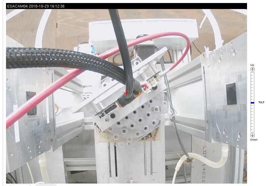
| Run 781-782 B53 Tilt position from CAM. Beam R->L. | Dec/15 6:41am remiss of Run 781-782 config. Beam L->R. |
 |  |
| For Run 781-782 with B53. Beam Up->Down at 87deg. | Dec/15 6:45am. A97 mounted, before Run 785. |
6:35 Requested access to change DUT to A97 (25x100um pixel). and mounted at 0 degrees. Also checked the Trg-10 NIM signal - now back. Remeasured the B53 tilt position before switching to A97. While the DUT plane angle to beam was fairly precisely measured at 55deg. The Longitudinal position is not easy to determine from photos. A very rough estimate was the DUT center was ~213mm after 3rd EUDET plane. New 0 deg DUT A97 with tape clip z~198.5mm implies ~196mm after 3rd EUDET plane.
8:10 Lowered particle rate to ~4 clus/mimosa and 0.6/pulse on RD53a 2/3 FE area. Hit spread pretty uniform.
8:16 Started low rate run 789. Beam spot X looks a bit off - centered at 340.
8:40 Stoped Run 789. Moved RD53a DUT by X+4mm.
8:42 New run 790 after DUT +x move.
9:00 MCC called to take away beam briefly for primary beam energy change. Will still come back to ~12.2 GeV secondary.
Data with A97
| Run | Start | End | Event | Particle rate | Tilt | Comments |
|---|---|---|---|---|---|---|
| 785 | 7:26 | 8:00 | 10015 | 42 | 0 | First run with DUT=A97 and new event counter follow TLU |
| 789 | 8:16 | 8:40 | 7205 | 0.65 | 0 | First low rate run for offline |
| 790 | 8:42 | 9:03 | 6180 | 0.75 | 0 | New run after DUT x+4mm move. |