Search/Navigation:
Related:
SLAC![]() /EPP
/EPP![]() /HPS Public
/HPS Public![]()
Jefferson Lab![]() /Hall B
/Hall B![]() /HPS Run Wiki
/HPS Run Wiki![]()
S30XL-LESA/LDMX
The laser test stand uses a pair of Class 3R laser sources with Class 1 fiber beam delivery to experimental equipment. If the requirements for operation (see below) are met, the system is designed to meet Class 1 safety limits.
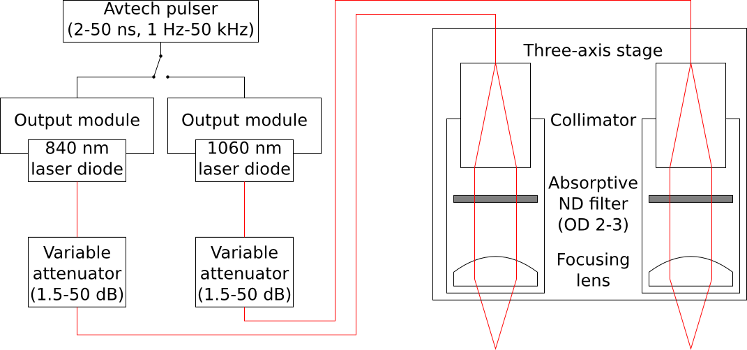
Laser diodes are bonded at their outputs to fiber pigtails connected to the beam delivery path. The diodes can only be powered using the output modules listed below.
AVTech Electrosystems AVO-9A-B-P-P3-SLAA with output modules AVX-S1-P3-SLAA (for the 840 nm diode) and AVX-S1-P4B (for the 1040 nm diode).
Pulse generator has maximum pulse amplitude 10 V (200 mA into the 50-ohm impedances of the output modules) and maximum duty cycle 0.0025 (50 ns * 50 kHz).
The laser diode pigtails are connected through adjustable fiber attenuators to the optical system (collimator, absorptive neutral density filter, and focusing lens) on the three-axis stage. The laser light is confined to a optical fiber or a sealed lens tube at every point from the laser diode to the exit of the focusing lens.