About this version of CSPad alignment
- Sensors in quads are aligned individually (see CSPad Alignment of quads) using their natural coordinates as from the optical measurement (top-left corner is an origin, nearest point to the beam spot).
- Quads are rotated and inserted in uniform 2-D array with appropriate offsets.
Earlier versions of CSPad alignment
CSpad Alignment - v2011-05-25
CSPad Alignment of quads - v2011-06-14
CSPad Alignment of quads
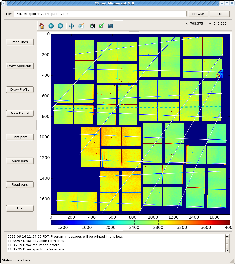
Alignment tool
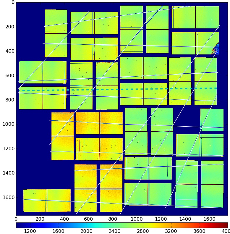
- Takes image of CSPad or quad from 2-D array
- Draw lines along the wire shadows
- Interactively adjust lines along the wire shadows
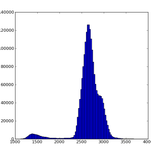
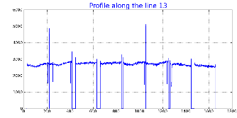
- Plots:
- image
- image profile
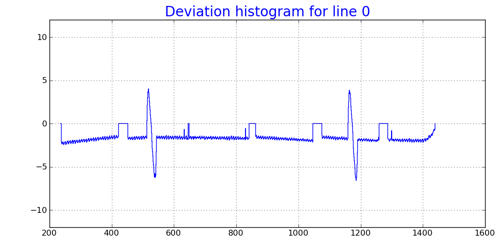
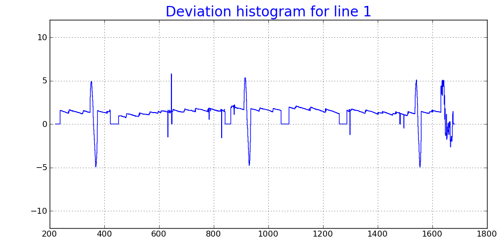
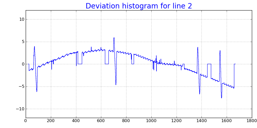
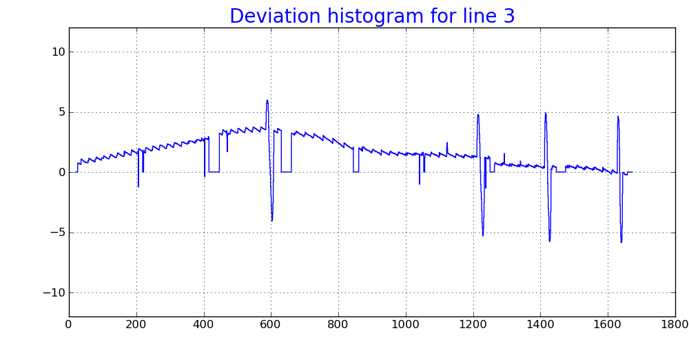
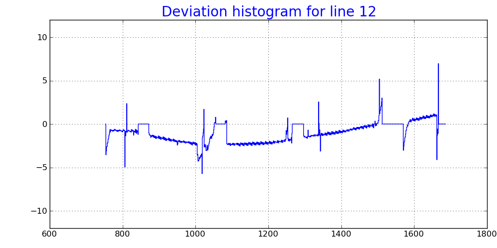
- deviation of the shadow "center of gravity" from line along the line
Alignment parameters
Alignment of sensors in quads
See CSPad Alignment of quads for sensor position parameters in quads.
Quad nominal rotation angle (dergee)
self.quadInDetOrient = [180, 90, 0, 270]
Quad corner X and Y coordinates (in pixel)
    off    = 30
    gapX   =  0
    gapY   =  0
    shiftX = 18
    shiftY = 18

    quadXOffset = [ off+0-gapX+shiftX,  off+  0+1-gapX-shiftX,  off+834+0+gapX-shiftX,  off+834+0+gapX+shiftX]
    quadYOffset = [ off+0-gapY-shiftY,  off+834-3+gapY-shiftY,  off+834-0+gapY+shiftY,  off+  0+2-gapY+shiftY]
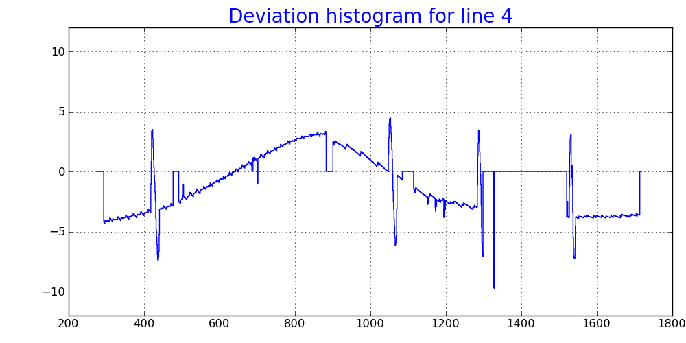
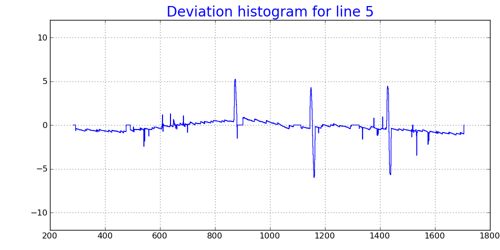
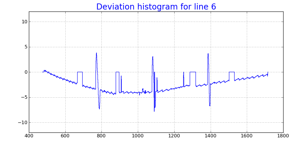
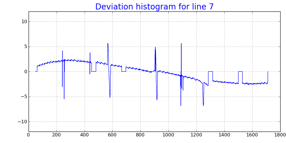
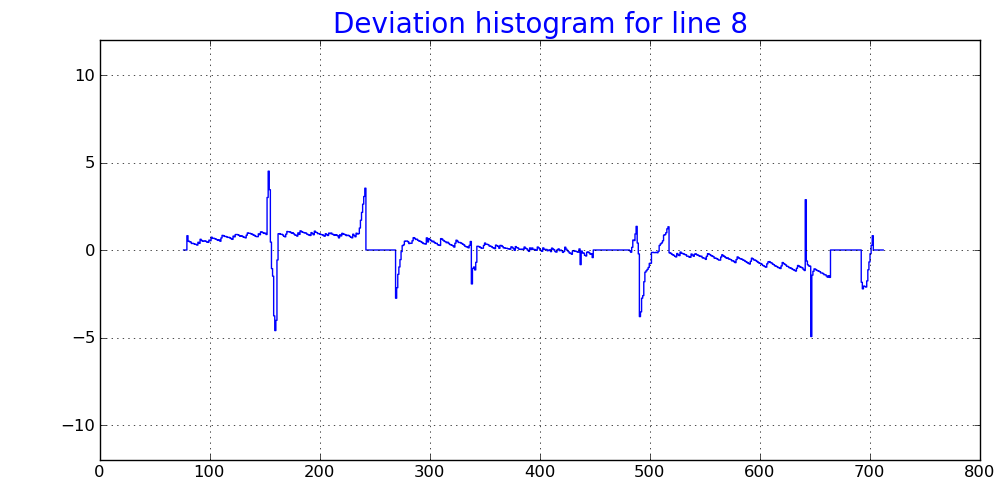
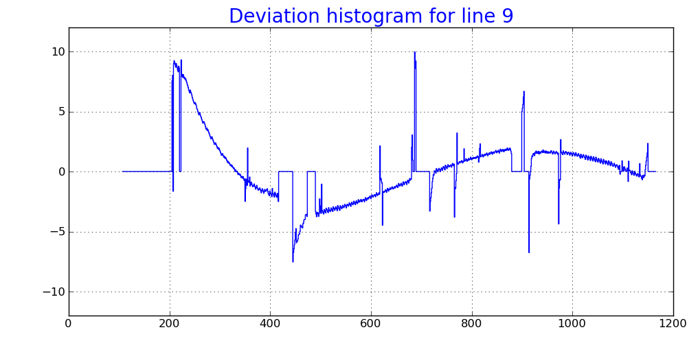
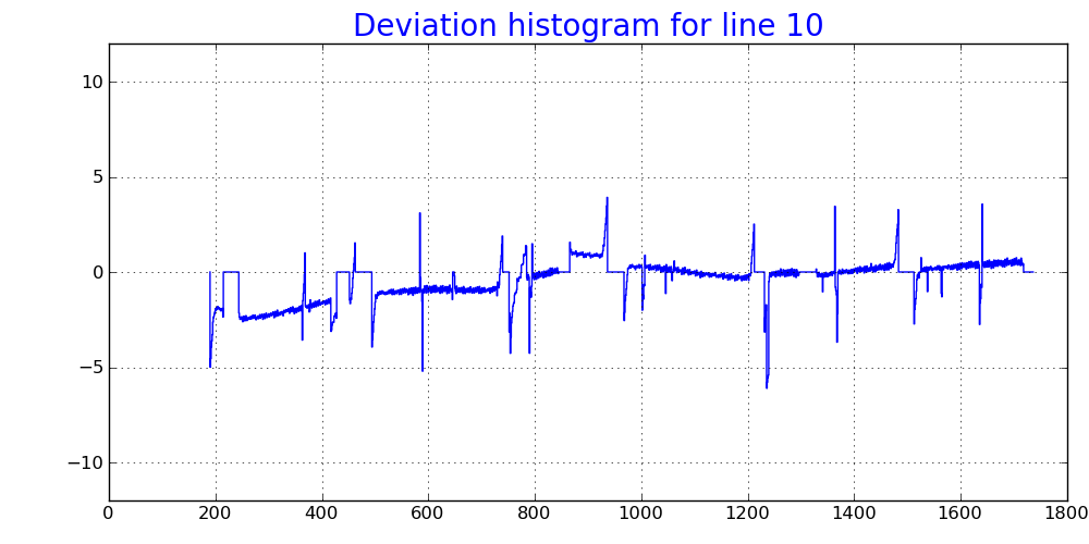
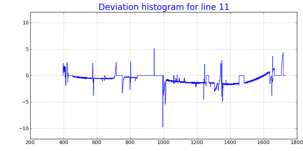
Deviation of the wire shadows from lines
Overview
Content Tools