Issues to consider:
- current configuration time is long at 34s
- fiber-power monitoring on the detector side and kcu1500
- have to manually lock the lanes between ASICs and managing FPGA
- not all lanes in an ASIC lock (can perhaps be fixed with improved delay settings)
Auto-ranging, cannot be run in fixed-range mode (maybe Lorenzo is thinking about this?)
GitHub repo: https://github.com/slaclab/epix-hr-m-320k (currently using branch tempRelease)
Using XilinxKcu1500Pgp4_10Gbps mcs files from pgp-pcie-apps GitHub repo
(need to run from the "script" directory at the moment) python devGui.py --serverPort 9200 --pciePgpEn 1 (zmq port defaults to 9100, but that port was in use in the test stand)
currently has 4 ASICs in a 2x2 configuration (one piece of silicon). the size of the ASIC is 192*384 columns (more than twice as big as EpixHR ASIC)
each ASIC is its own lane
firmware defaults to LCLS-II timing
Need to ask Chris Kenney or Lorenzo about precise panel geometries so Mikhail can support the geometry in psana2
need this setting in devGui under "Root":
![]()
3 means 168MHz clock, and the 4 1's initialize (includes a reset plus configuration) the ASICs, which includes loading config files: the config files that are used are in config/ePixHRM320k_ASIC_u1_PLLBypass.yml (and u2,u3,u4 for other ASICs). Currently the 4 configurations are identical, apart from a module name. Also configures the firmware of a single "managing" FPGA (e.g. batching event-builder).
Issue: the serial links between the managing FPGA and the ASICs don't always lock until a number of frames have been transmitted (may want to fix this more robustly in the long-term). Short-term workaround: call root.hwTrigger(frames, rate) for ~1000 frames at rate 1000 (1kHz).
Currently the data needs to be descrambled in software. There is a plan to eventually descramble in firmware.
Plan: run the software/notebook/maximumRateTest.ipynb
Introductory script
### Setup the library ###
import pyrogue as pr
import os, sys
import matplotlib.pyplot as plt
import time
import datetime
import numpy as np
import math
import pprint
import inspect
top_level=f'{os.getcwd()}/../'
rootTopLevel = top_level+'script/'
pr.addLibraryPath( rootTopLevel )

import setupLibPaths

import ePix320kM as devBoard

args = None

# ONLY RUN ONCE!
# Defining root
root =  devBoard.Root(
        top_level  = rootTopLevel,
        dev        = '/dev/datadev_0',
        pollEn     = False,
        initRead   = True,
        serverPort = 9099,
        pciePgpEn  = True,
)
root.start()

# example showing a read
AxiVersion = root.Core.AxiVersion
print ( '###################################################')
print ( '#             Firmware Version                    #')
print ( '###################################################')
AxiVersion.printStatus()
print ( '###################################################')

# Useful short names
APP  = root.App
AXIV = root.Core.AxiVersion
ASICTOP = APP.AsicTop
TRIG = ASICTOP.TriggerRegisters
ASIC0 = APP.Mv2Asic[0]
ASIC1 = APP.Mv2Asic[1]
ASIC2 = APP.Mv2Asic[2]
ASIC3 = APP.Mv2Asic[3]
HSDAC = APP.Dac.FastDac
PKREG = [None] * 4
PKREG[0] = ASICTOP.DigAsicStrmRegisters0
PKREG[1] = ASICTOP.DigAsicStrmRegisters1
PKREG[2] = ASICTOP.DigAsicStrmRegisters2
PKREG[3] = ASICTOP.DigAsicStrmRegisters3
BATCHER0 = ASICTOP.BatcherEventBuilder0
BATCHER1 = ASICTOP.BatcherEventBuilder1
BATCHER2 = ASICTOP.BatcherEventBuilder2
BATCHER3 = ASICTOP.BatcherEventBuilder3
DEBUG0 = root._dbg[0]
DEBUG1 = root._dbg[1]
DEBUG2 = root._dbg[2]
DEBUG3 = root._dbg[3]
DATARCV0 = root.DataReceiver0
DATARCV1 = root.DataReceiver1
DATARCV2 = root.DataReceiver2
DATARCV3 = root.DataReceiver3
FULLRATERCV0 = root.fullRateDataReceiver[0]
FULLRATERCV1 = root.fullRateDataReceiver[1]
FULLRATERCV2 = root.fullRateDataReceiver[2]
FULLRATERCV3 = root.fullRateDataReceiver[3]
DAC = APP.Dac
REGCTRL = ASICTOP.RegisterControlDualClock

# Configure clock to 168 MHz and configures all ASICS
root.InitASIC([3,1,1,1,1])

# disable some software rogue data receivers
root.disableAndCleanAllFullRateDataRcv()
root.enableDataRcv(False)
root.enableDataDebug(False)

#run some triggers and exercise lanes and locks
frames = 5000
rate = 1000

root.hwTrigger(frames, rate)

#get locked lanes
root.getLaneLocks()

#Enable data receivers and run some triggers
root.enableDataRcv(True)
root.enableAllAsics(True)
root.Trigger() # one event via software trigger

# Obtain descrambled single frame data from ASICs from DataReceiver. Data receiver is do
wn sampled.
root.printDataReceiverStatus()

frame = [None for i in range(4)]
for asicIndex in range(4):
    frame[asicIndex] = getattr(root, f"DataReceiver{asicIndex}").Data.get()

#frame dimensions
for asicIndex in range(root.numOfAsics):
    print(np.shape(frame[asicIndex]))

#plot image
plt.subplots(2,2,figsize=(17,17))
for asicIndex in range(root.numOfAsics):
    if asicIndex == 3 :
        plt.subplot(2,2,3)
    elif asicIndex == 2 :
        plt.subplot(2,2,4)
    else :
        plt.subplot(2,2,asicIndex+1)

    if np.shape(frame[asicIndex])[0] != 1 :
        plt.imshow(frame[asicIndex])
        plt.xlabel("ASIC {}".format(asicIndex))
        plt.colorbar()
    else :
        plt.xlabel("ASIC {}: No data".format(asicIndex))
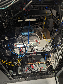
Teststand: (timing is left fiber, registers are on middle MPO8 fiber, data is on right MPO8 fiber)
To lock the lanes:
App->AsicTop->TriggerRegisters→SetAutoTrigger (set to 1000 and hit enter)
numberTrigger set to 5000
StartautoTrigger (exec)
Do "Read All" at the bottom and check that AcqCount and DaqCount are 5000
StopTriggers
View state of locks with App→SspMonGrp[0:3] look at "Locked" register. Total of 24 lanes in each asic (should be 0xffffff). Can still run even if not all links are locked: disable lanes that are not functioning. Saw between 0 and 6 lanes not locked for asics 0-3. Mostly reproducible failing lane numbers.
App->AsicTop→DigAsicStrmRegisters[0:3] set "DisableLane" to turn off non-locked lanes. A single unlocked lane that is not disabled will prevent frames from being transmitted by firmware.
Enable the software receivers via DataReceiver[0:3] with RxEnable. Hit "Trigger" to generate one software trigger. In principle can view an image with DisplayViewer[0:3], but saw a pydm error when we tried this.
To run with XPM triggers, go to the usual TriggerEventManager→TriggerEventBuffer[1] and set "Partition" to the readout group: this is the DAQ trigger. TriggerEventBuffer[0] is the Run Trigger.
To see trigger counts go to AsicTop→TriggerRegisters and EXEC "SetTimingTrigger" and then do a "Read All" to watch for counters to increment (AcqCount and DaqCount). Did two things: set TriggerEventBuffer[0] (the run trigger) to also fire on the readout group and set AsicTop->TriggerRegisters→PgpTrigEn to True and then we saw it count. AcqCount counts run triggers, and the DaqCount counts daq triggers. Can see it in the DataReceiver "FrameCount"
Overview
Content Tools