...
The LCLS-SC Cryogenic System consists of two cryoplants in one very large building just north of the klystron gallery sector 4, the distribution system (piping to distribute helium gas at various temperatures), and cryomodules. I highly recommend the Cryoplant Overview by Eric Fauve 8/27/21.


The output of the cryoplants is gaseous helium of various temperatures in different pipes in one large pipe called the distribution line which runs across the north gallery road. The pipe feeds into the two distribution boxes which then feed into two distribution lines that goes into the accelerator housing. One goes west and feeds into the pipes (cryo lines) in L2B. At the west end of L2B is an "end cap" which transitions the cryo lines back to the distribution line which bends up to the ceiling to go over BC1B before descending and joining the L1B "feed cap". The cryo lines go through L1B then through the end cap back to a distribution line that goes over the laser heater before going to L0B. At the far west end of L0B is an end cap where some of the cryo lines turn around.
The output of the downstream distribution box goes downstairs to the L3B feed cap. In the middle of L3B is a vacuum barrier - a location with vacuum equipment for the insulating vacuum. At the east end of L3B is an end cap where some of the cryo lines turn around.

Cryomodule Cryo Pipes or Lines
The gaseous helium of various temperatures is contained in pipes that run through each cryomodule. All but two of the cryo pipes in a given cryomodule are welded to its neighboring cryomodules' cryo pipes in a linac section (L1B, L2B, or L3B).
This slide shows a drawing of the cryomodule cross section and a photo of a cryomodule cold mass before it was inserted into the vacuum vessel. At the top right is image shows a cross section drawing of a cavity in its helium vessel showing the cooldown line feed ports at the bottom and the chimney connection to the two-phase pipe at the top.
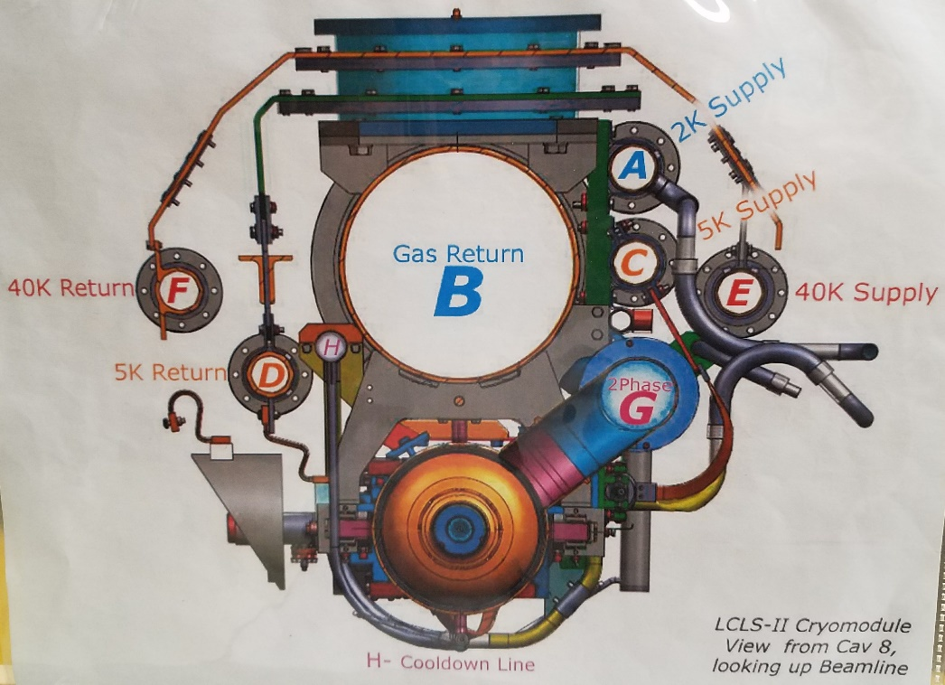
The cryo lines' functions are as follow:
- Line A "2K Supply" carries gas about 2K that is sent through a JT valve to create liquid for cooling the cavities
- Line B "Gaseous Helium Return Pipe (GHRP)" 300 mm gas return pipe used to return the evaporated helium from around the cavities back to the cryoplant to be re-cooled
- Line C "5K Intercept Supply" many devices in the cryomodule are thermally strapped to this ~10cm pipe to cool them to 5K.
- Line D "5K Intercept Return" Line C makes a U-turn in the far end caps (west end of L0B and east end of L3B) and the now warmer gas returns to the cryoplant in line D.
- Line E "50K Intercept Supply" Similar to line C but carries warmer gas. Many devices and the thermal shield are thermally strapped to this line.
- Line F "50K Intercept return" Similar to line D but carries the return from Line E.
- Line G "Two phase pipe" This pipe is connected to the chimneys of the cavities' helium vessels. The output of the JT valve feeds to this line where the liquid is collected around the cavities until the cryomodule has so much liquid that the level is about halfway up the two phase pipe and the cavities are fully submerged. Line G is one of the two pipes that is not welded to the neighboring cryomodule. Each cryomodule has its own line G.
- Line H "Cooldown line" The output of the cooldown JT valve feeds into this line. At each cavity in the cryomodule there is a drop down from line H to feed the cavity from below.
A summary cryomodule monitoring panel is available via the control system in ACR by selecting a specific cryomodule from LCLS Home → Lx. The various cryo lines are shown in cartoon form on this screen:
which can be reached from lclshome, then any of the LxB cryo boxes, then select a specific cryomodule.
This slide shows the cavity helium vessel, the chimney to the two-phase pipe, and the cooldown line feed ports at the bottom of the helium vessel. 

Cryomodule Cryo Diagnostics
...