Most slide images are from Janice's talk on 31 Aug 2021.
Why Cryo?
If you want superconducting cavities (see SRF Intro on MCC wiki) at 2K, such things can't be next to 300K air - all the liquid helium would boil. Instead the cavities in their helium vessels (titanium jackets that allow an accumulation of liquid helium around the cavities) are deep within a cryomodule. The components of a cryomodule are progressively cooled from 300K room temperature (the exterior vacuum vessel) to 2K liquid helium around the cavity.
Cryoplants & Distribution System
The LCLS-SC Cryogenic System consists of two cryoplants in one very large building just north of the klystron gallery sector 4, the distribution system (piping to distribute helium gas at various temperatures), and cryomodules. I highly recommend the Cryoplant Overview by Eric Fauve 8/27/21.

The output of the cryoplants is gaseous helium of various temperatures in different pipes in one large pipe called the distribution line which runs across the north gallery road. The pipe feeds into the two distribution boxes which then feed into two distribution lines that goes into the accelerator housing. One goes west and feeds into the pipes (cryo lines) in L2B. At the west end of L2B is an "end cap" which transitions the cryo lines back to the distribution line which bends up to the ceiling to go over BC1B before descending and joining the L1B "feed cap". The cryo lines go through L1B then through the end cap back to a distribution line that goes over the laser heater before going to L0B. At the far west end of L0B is an end cap where some of the cryo lines turn around.
The output of the downstream distribution box goes downstairs to the L3B feed cap. In the middle of L3B is a vacuum barrier - a location with vacuum equipment for the insulating vacuum. At the east end of L3B is an end cap where some of the cryo lines turn around.


Cryomodule Cryo Pipes or Lines
The gaseous helium of various temperatures is contained in pipes that run through each cryomodule. All but two of the cryo pipes in a given cryomodule are welded to its neighboring cryomodules' cryo pipes in a linac section (L1B, L2B, or L3B).
This image shows a cross section drawing of a cavity in its helium vessel showing the cooldown line feed ports at the bottom and the chimney connection to the two-phase pipe at the top.
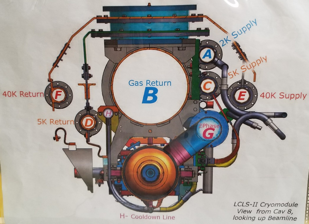
The cryo lines' functions are as follow:
- Line A "2K Supply" carries gas about 2K that is sent through a JT valve to create liquid for cooling the cavities
- Line B "Gaseous Helium Return Pipe (GHRP)" 300 mm gas return pipe used to return the evaporated helium from around the cavities back to the cryoplant to be re-cooled
- Line C "5K Intercept Supply" many devices in the cryomodule are thermally strapped to this ~10cm pipe to cool them to 5K.
- Line D "5K Intercept Return" Line C makes a U-turn in the far end caps (west end of L0B and east end of L3B) and the now warmer gas returns to the cryoplant in line D.
- Line E "50K Intercept Supply" Similar to line C but carries warmer gas. Many devices and the thermal shield are thermally strapped to this line.
- Line F "50K Intercept return" Similar to line D but carries the return from Line E.
- Line G "Two phase pipe" This pipe is connected to the chimneys of the cavities' helium vessels. The output of the JT valve feeds to this line where the liquid is collected around the cavities until the cryomodule has so much liquid that the level is about halfway up the two phase pipe and the cavities are fully submerged. Line G is one of the two pipes that is not welded to the neighboring cryomodule. Each cryomodule has its own line G.
- Line H "Cooldown line" The output of the cooldown JT valve feeds into this line. At each cavity in the cryomodule there is a drop down from line H to feed the cavity from below.
A summary cryomodule monitoring panel is available via the control system in ACR by selecting a specific cryomodule from LCLS Home → Lx. The various cryo lines are shown in cartoon form on this screen:

Cryomodule Cryo Diagnostics
The most critical cryo diagnostics for SRF running are those that show that the cavities are submerged in liquid and that the liquid is superfluid.
Liquid Level Cans
At each end of the two phase pipe are "liquid level cans" - tubes about 30 cm long and 10 cm wide that contain a wire taped to a piece of plastic about the size of a ruler. In the two phase pipe slide above, in the upper photo is you can see the upstream liquid level can and in the lower photo you can see the downstream one. As liquid helium fills the two phase pipe, it also flows and fills these cans in addition to the helium vessels around the cavities. The resistance of the wire is measured. If the wire were entirely in 300K air its resistance would be much higher than if it were entirely submerged in 2K liquid helium. So one can use the amount of resistance to calculate the amount of the wire that is submerged - giving a measurement of the depth of the liquid helium at that location. In the cryomodule instrumentation display above, the liquid level sensor readings are circled in yellow.
Typical Readings
Because the accelerator housing is tilted downstream by 0.5%, the liquid level will be higher in the downstream can than the upstream can. Typical numbers expected are 90-95% in the downstream can and 80-85% in the upstream can. If the liquid level in the upstream can reads about 65%, the liquid is just at the point where the bottom of the two phase pipe is joined to the upstream can and if liquid continues to evaporate, there's a risk that cavity 1 will no longer be submerged (at which point it will no longer be superconducting and will quench).
Pressure Sensors
The pressure of the helium gas in the two phase pipe is proportional to the temperature of the liquid. Each cryomodule has two pressure sensors on the two phase pipe - one on each end of the cryomodule. The one on the upstream end is less accurate but reads from 0 to 6666 mbara (5000 Torr). The downstream pressure sensor is more sensitive, but only reads from 0 to 133 mbara (100 Torr). In the cryomodule instrumentation display above, the pressure sensors readouts are circled in green.
Typical Readings
When the cavities are about 2K, the pressure is about 32 mbara (24 Torr). If this readings gets above 46 mbara (35 Torr), the cavities can quench. The lambda point of liquid helium (when it ceases to be superfluid) is 2.17K at 1 atm. Liquid helium boils at 4.2K.

from Helium Vapor Pressure Temperature Calculator
Coupler and Stepper Motor Temperatures
Each coupler has two temperature sensors - one at 12 o'clock (top) and one at 6 o'clock (bottom). If these get too hot (>100K? we'll have to see), they indicate that there is a problem with the coupler - either its thermal strapping is no longer working or the coupler is tuned incorrectly. There is also a sensor on each cavity's tuner stepper motor. If these overheat (>100K?), it indicates a problem with the motor or its thermal strapping. These signals are interlock inputs to the LLRF system and will trip the RF if they get too high. On the instrumentation display (above) these are in the big red box.
From Curt Hovater's Feb 2019 talk:

Other Temperature Sensors
- Cryo lines A, C, D, E, and F each have one temperature sensor on them.
- Cryo line B has two sensors - one on the top and one on the bottom.
- There is one temperature sensor on the upper shield.
- There are two temperature sensors on each of the helium vessels for cavities 1 & 5, top and bottom.
- There are temperature sensors on the magnet coils and leads
- There are two temperature sensors on the U-turn in line H just below the cooldown JT valve near the heater.
These are in red boxes or circles in the instrumentation display above.
Vacuum Gauges
Each cryomodule has three vacuum spaces - the insulating vacuum around the components, the vacuum manifold connected to the vacuum space in each coupler, and the beamline vacuum.
- The insulating vacuum is measured by a combination vacuum gauge at the interconnect between every other cryomodule (that is there's a gauge set between cryomodules 4 & 5 and the next one is between cryomodules 6 & 7). A combination vacuum gauge in this instance is a pair of gauges - a pirani and a cold cathode. Depending on the vacuum level, one or the other is more accurate. The combination gauge in an EPICS construct that displays the reading from the right gauge depending on the vacuum quality.
- On each cryomodule coupler vacuum manifold there is a vacuum pump and a combination vacuum gauge. The manifold connects the vacuum spaces in the individual couplers
- The beamline vacuum is measured by many gauges in the warm beamline sections. At each end of the linac sections (L0B, L1B, L2B, and L3) is a beamline section with many vacuum components - gauges, valves, and pumps. The beamline within the cryomodules is "cryopumped" - meaning any gas freezes to the walls of the cavities. If there was a break in the beamline allowing air to enter a cryomodule, all the gases and dust etc would get in the cavities making them unable to sustain RF fields. Thus that region is critical from a vacuum point of view.
The beamline maps (at least L1B and downstream as of this writing) show the vacuum components accurately.
In the photo you can see the coupler manifold - the round silver pipe below the couplers: 
Screen grab of beamline map showing the downstream end of L2B and the vacuum raft:

On the instrumentation display, the vacuum readings are circled in orange. The plan is to have three readings for each cryomodule: the nearest insulating vacuum gauge, the coupler manifold gauge, and the nearest beamline vacuum gauge.
Typical Readings
The anticipated vacuum levels are 10-5 T insulating vacuum, 10-8 coupler vacuum, and 10-9 or 10-10 beamline vacuum.