...
PLC Installation
Module Installation

- Connect 28-pin cable (circled in blue) from each input/output module to its corresponding input/output terminal block.
- Connect cable from 15-pin port on PLC module (circled in orange) to 9-pin port on RS232 converter (pictured below).

- Wire positive and negative terminals (circled in green) to those of the Quint Power Supply Unit (pictured below).

Installing and Connecting Breakout Modules
...
- Download the software installer from https://support.automationdirect.com/products/directsoft.html.
- Install the latest version of DirectSoft.
- License Key: QKGD-6L68-Y019-J117
Connecting to the PLC

- Plug HDMI cable into Port 1 (circled) of PLC module.
- USB adapter will be needed to connect to computer.
- PLC must be in terminal mode ("TERM") to transfer changes.
- In the DirectSoft program, go to PLC > Connect...
- If the PLC has never been connected to the computer before, create link.
- Select Link... > Add...
- Select the communications port that the PLC is connected to.
- This may be found in the Device Manager of your computer’s Control Panel
- Select the PLC’s product family.
- Example: DirectLogic205 will be from the DL 0/1/2/4/350 Family
- Select the protocol to use in the communications link.
- SLAC LSS uses K Sequence
- Address: 1
- In the “Select Link…” pop-up window, click on the PLC you are using and press “Select”.
...
- Mounting and Connecting to Power
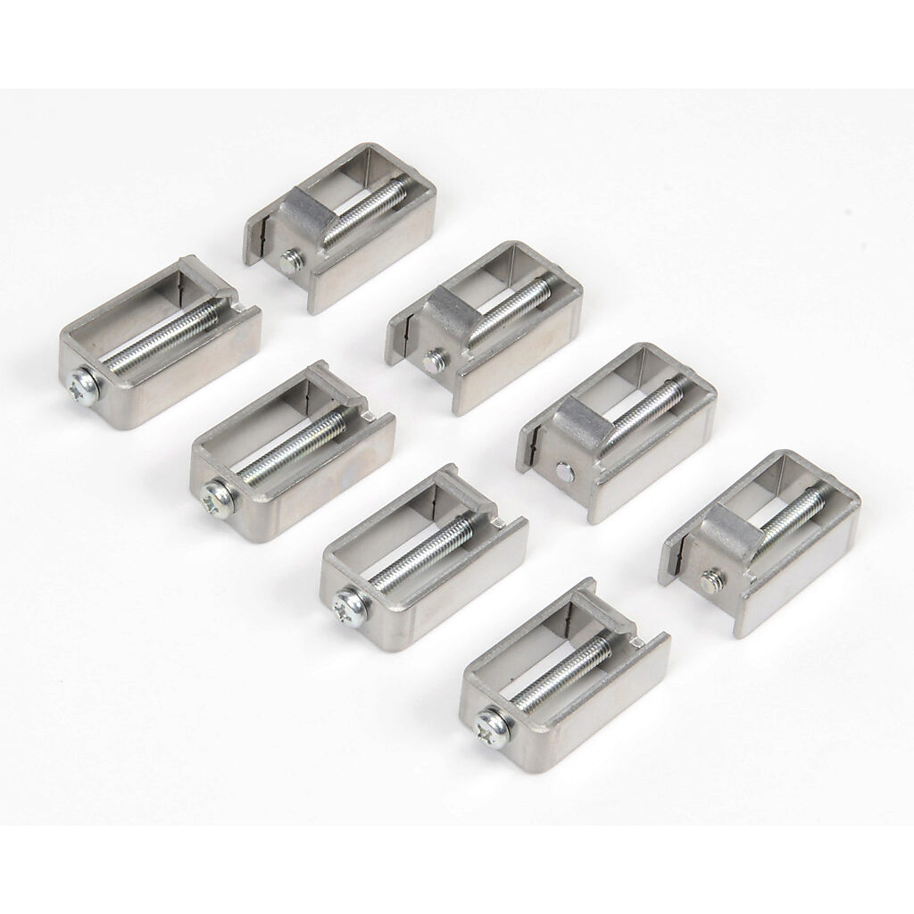
- The C-more touch panel order with come with the touch screen, mounting clips, and a terminal block.
- Use the mounting clips (pictured below) to secure the panel, from the inside, to LSS box door.
- Secure terminal block to back of panel.
- Connect one black wire (GND) from the ground terminal to grounded contact on rack.
- Ground terminal is second from the bottom and will be labelled with the ground symbol.
- Connect one blue wire (power) from the negative terminal to 24V contact on rack.
- Negative terminal is third from the bottom and will be labelled with a minus sign.
- Connecting to the PLC
- Connect HDMI cable from 15-pin port on back of panel to Data Communications Module port (pictured below).

- Connect HDMI cable from 15-pin port on back of panel to Data Communications Module port (pictured below).
- Connecting to Computer
- To upload new code, connect USB Cable from port on back of panel to port on computer.
...