Page History
...
| Note |
|---|
|
...
with default options produce 2-d image from ndarray of sensors' data and save it in the file mask-img.txt, Fig.1. In the 1st command the ndarray file name (option -a) is omited and the mask of sensors is created. Option -c sets the bit control word to remove edge, central, non-bound, etc. pixels in the mask.
...
Fig.2: Mask editor GUI for drawing the ROI (left) and when the mask is saved (right).
Then, use mouse and buttons to draw the mask and, when it is ready, click the button "Save Mask". By default the file mask-roi.txt is saved with content shown in Fig.32 (right).
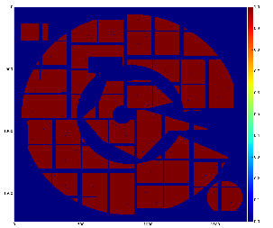
Fig.3: Graphical content of the file mask-roi.txt.
Convert ROI mask to ndarray with mask shaped as data
...
by default converts the file mask-roi.txt to mask-nda.txt. Algorithm uses sequential numeration of sensor pixels, shown by color in Fig.4 (left) with following mapping of pixel ROI mask content with ndarray, presented in Fig.4 (right) in specific for CSPAD shape. As a cross-check this ndarray can be converted back to the image using geometry file, as shown in Fig.5.
![]()
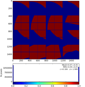
Fig.4: Mask on the top of enumerated (color-coded) pixels (left) and result of the mask conversion to the ndarray (right).
Fig.5: Cross-check: ndarray with mask is converted to the image using geometry file.
Usage of ndarray with ROI mask
...
...
Overview
Content Tools