Page History
...
- use the same coordinate system as in optical measurements,
- apply minimal offset (translation) to optical frame in order to make all coordinates positive (see left plot below),
- use averaged coordinate af of all tiles (see right plot below),
- use user-defined translation, for example set origin in the evaluated point of beam crossing with the detector plane.
...
Pixel coordinate reconstruction in the detector frame uses
- tile ideal geometry,
- tile center positions,
- tile N·90 rotation and tilt angles:
(x,y,z)in detector = (Xc,Yc,Zc) + RotationR(N·90+tilt) × (x,y,z)in tile,
where rotation matrix R is a product of three rotations around appropriate axes, for example rotation in X-Y plane around Z is
/ cosT -sinT 0 \
Rz(T) = | sinT cosT 0 |
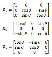 \ 0 0 1 /
Pixel coordinates in the detector should be accessed by method like
...
Overview
Content Tools