Page History
...
Content
| Table of Contents |
|---|
Coordinate system
...
for setup
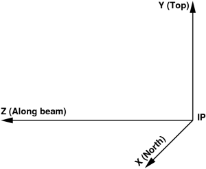
Axes definition
In most experiments the Cartesian coordinate system of setup is defined by the 3 three mutually orthogonal right-hand-indexed axes with origin in the interaction point (IP) of the photon beam with sample:
- X – pointing from IP to the north,
- Y – pointing from IP to the top, and
- Z – pointing from IP along the photon beam propagation direction.,
as shown in the plot:
| Info |
|---|
Each photon with sample collision happens in different place... IP is an abstract position of the crossing point of the "beam line" and "target", which both are not well defined... Is it really good definition? |
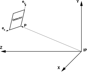
Detector position
Detector coordinate system may have a translation and rotation with respect to the setup, which are can be defined by the 3 vectors in the setup frame:
- P – translation vector pointing from IP to the detector origin,
- ex – unit vector along the detector frame x axis,
ey – unit vector along the detector frame y axis.,
as shown in the plot:
Third unit vector ez – is assumed to be right-hand triplet component,
...
Components of these three unit vectors forms form the matrix e, where indexes "i" and "j" corresponds to the vector components in the setup and detector local coordinate frames, respectively. Within this definition 3-d pixel coordinate "c" from in the detector frame can be easily transformed to the setup coordinate "C":ij
Ci=eij·cj + Pi.
Tile ideal geometry
Coordinate system of the detector
In this note we assume (although it is not necessary for most of algorithms) that:
- Assume that the detector image is produced by a set of tiles (a.k.a., segment, section, 2x1, sensor, Si-pixel matrix, etc),
- the tiles form almost flat (x-y) surface around z=0 within precision of production technology and installation,
- the tile rotation angles in (x-y) are N*90 degrees, where N=0,1,2,or 3,
- detector local coordinate system is defined in this plane, as explained below.
Tile ideal geometry
- Each tile has well defined by design geometry of pixels, which does not need in separate calibration.
- Pixel center (x,y) center coordinate coordinates at z=0 for each tile can be defined as a look-up table in its "natural" matrix-style coordinate system.
- For example, CSPAD 2x1 tile pixel geometry is defined as
...
Suggested method for imaging detector geometry description provides simple and unambiguous way of pixel coordinate parametrization. This method utilizes all available information from optical measurement and design of the detector and tiles. All geometry parameters are extracted without fitting technique and presented by natural intuitive way.
Overview
Content Tools