Page History
...
Proposal for precise geometry parametrization of planar imaging detectors.
Content
| Table of Contents |
|---|
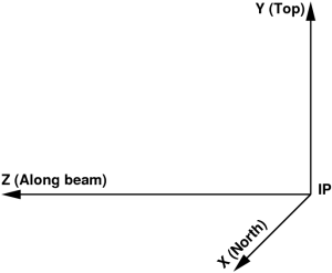
Coordinate system at interaction point
In most experiments the Cartesian coordinate system is defined by the 3 mutually orthogonal right-hand-indexed axes with respect to the interaction point (IP) of the photon beam with sample:
Tile ideal geometry
- Assume that the detector image is produced by a set of tiles (a.k.a., segment, section, 2x1, sensor, Si-pixel matrix, etc).
- Each tile has well defined by design geometry of pixels, which does not need in separate calibration.
- Pixel (x,y) center coordinate at z=0 for each tile can be defined as a look-up table in its "natural" matrix-style coordinate system.
- For example, CSPAD 2x1 tile pixel geometry is defined as:
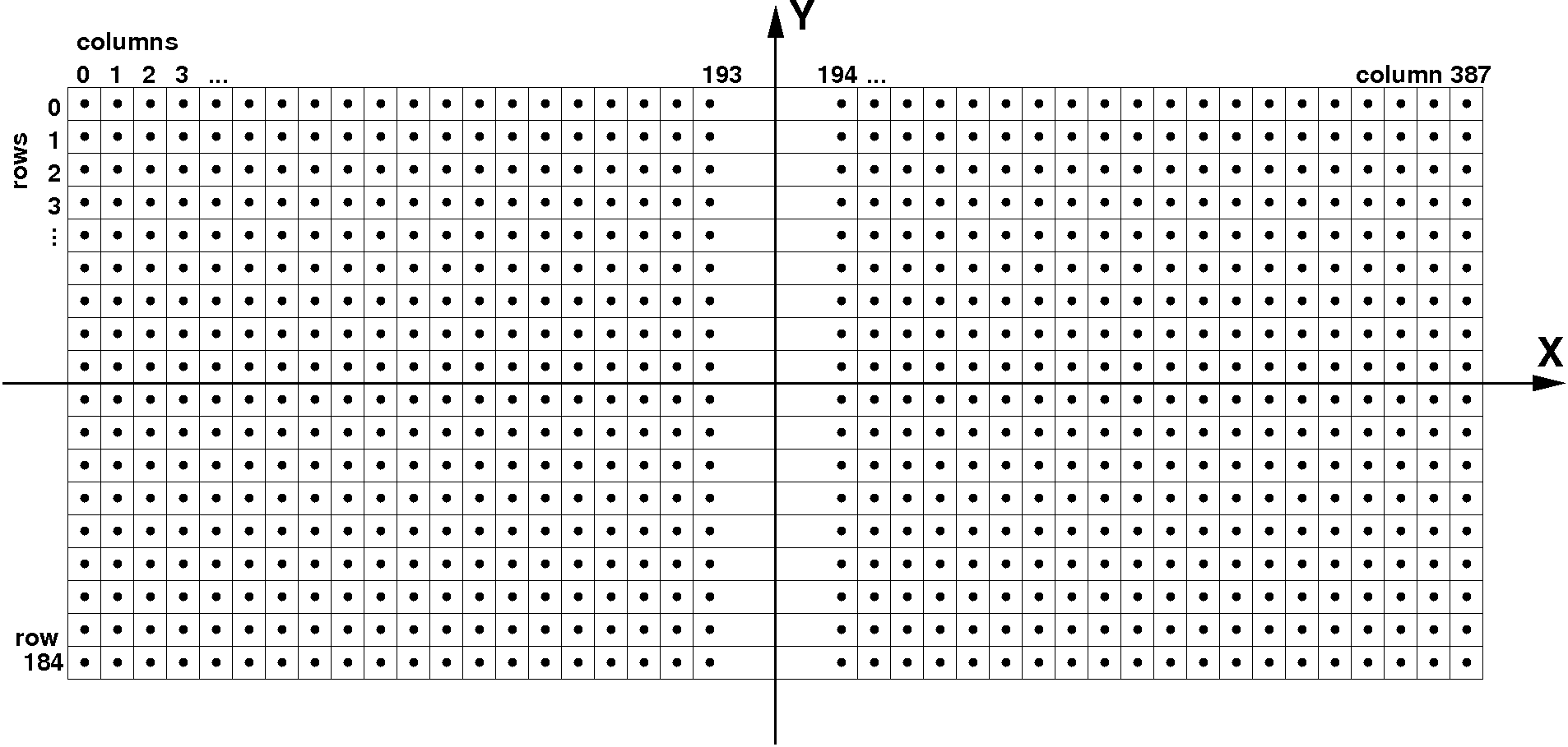
- Pixel index in 2x1 memory block (185x388) is:
i = col + row*388
| Code Block | ||
|---|---|---|
| ||
     (Xmin,Ymax)      ^ Y          (Xmax,Ymax)
     (0,0)            |            (0,387)
        ------------------------------
        |             |              |
        |             |              |
        |             |              |
      --|-------------+--------------|----> X
        |             |              |
        |             |              |
        |             |              |
        ------------------------------
     (184,0)          |           (184,387)
(Xmin,Ymin) (Xmax,Ymin) |
...
Overview
Content Tools