Page History
...
This quality check works well to catch significant typos in input table. In case of obvious typos input table can be corrected. When the quality check is passed successfully the alignment parameters are saved in and deployed under the calib directory as explained below.
Alignment
...
parameters from optical measurement
From optical measurement we extract coordinates of the center of each 2x1 sensor and its tilt angle, that populates the calibration types center and tilt, respectively.
The center coordinates are evaluated as an averaged over 4 corners measurements for each axis. Additional correction to the center coordinate center_corr can be applied if the optical measurement has (non-)obvious problems.
The tilt parameters are the same as "angle(deg)" from quality check results table. The tilt parameters are used along with rotation to completely define orientation of 2x1 in quad (for CXI) or in detector (for XPP).
Alignment of quads in the detector
For CSPad with fixed quad geometry (like in XPP) optical measurement of entire detector (should) produces complete information for geometry alignment.
For CSPad with moveable quads (like in CXI) quads relative position For CSPad with fixed quad geometry (like in XPP) optical measurement of entire detector (should) produces complete information for geometry alignment.
For CSPad with moveable quads (like in CXI) quads relative position needs to be adjusted through the alignment parameters for quads. It is usually done using typical images with diffraction rings, wires or other shading objects:
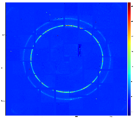
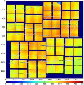
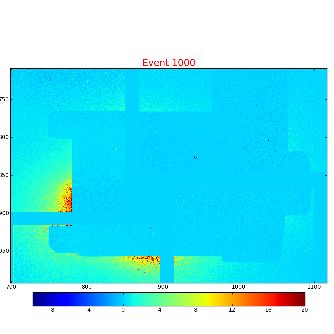
Although few algorithms of automatic quad alignment were tried, we did not find good generic way for automated quad tuning. Currently, the quad tuning parameters in marg_gap_shift and offset_corr are adjusted manually for runs with specific imagesimages.
Detector geometry model
In calibration parameters all coordinates are defined in terms of pixel size 109.92um. In this units the reserved square space for each quadrant is 850x850. The margins, shifts and gaps in marg_gap_shift are defined for these quads. The offset and offset_corr are defined for low-left angle of the rotated by n*90 degree quad. Size of entire CSPad image does not matter for this alignment.
Alignment parameters
Location of alignment parameters and file naming conventions
The official space for CSPad alignment parameters is
/reg/d/psdm/<INSTRUMENT>/<experiment>/calib/CsPad::Calib<VERSION>/<CSPad-name>/<type>/<run-range>.data
For example:
...
center- x, y, z center position of each 2x1 for all quadrants. Comes from optical measurement.center_corr- additional manual correction to the center parameter. Can be applied if the optical measurement has (non-)obvious problems.marg_gap_shift- margins, gaps, and shifts between quads, as explained below. Comes from image-based tuning.offset- x, y, z coordinates for 4 quads. Fairly-reasonable assigned before tuning of theoffset_corrandmarg_gap_shiftparameters.offset_corr- additional correction to the offset. Comes from image-based tuning.quad_rotation- 4 quad rotation in n*90 degree. Comes from basic geometry.quad_tilt- 4 quad tilt in fractional degree. Has never been used. In latest optical measurement is accounted through the global 2x1 coordinate measurement in the detector.rotation- 8 2x1-rotation angle for 4 quads in n*90 degree. Comes from basic geometry.tilt- 8 2x1-tilt angle for 4 quads in fractional degree. Comes from optical measurement.
...
- detector.
rotation- 8 2x1-rotation angle for 4 quads in n*90 degree. Comes from basic geometry.tilt- 8 2x1-tilt angle for 4 quads in fractional degree. Comes from optical measurement.
File format for calibration types
center
Tail of the path: center/<run-range>.data
Parameters: x,y,z coordinates of 8 2x1 centers in 4 quads in pixels:
...
Overview
Content Tools