Page History
...
| Anchor | ||||
|---|---|---|---|---|
|
2020-06-
...
10
Directories
/reg/d/psdm/det/detdaq18/xtc
/reg/d/psdm/det/detdaq18/calib/Epix10ka2M::CalibV1/DetLab.0:Epix10ka2M.0/pedestals/
/reg/g/psdm/detector/gains/epix10k/panels/
...
fit does not work for all injection points...


| Code Block | ||||
|---|---|---|---|---|
| ||||
Dubrovin, Mikhail Thu 6/11/2020 9:28 AM
To: Kwiatkowski, Maciej; Blaj, Gabriel
Hi Maciej,
I hope you are the right person to ask this question about epix10ka calibration.
I am trying to fix Gabriel's fitter which defines offsets between switching gain modes of epix10ka.
For some reason it does not work well for all pixels.
A few plots for new 2M detector recent run 40 are posted on
https://confluence.slac.stanford.edu/display/PSDM/EPIX10KA2M+Charge+injection+fit+issue#EPIX10KA2MChargeinjectionfitissue-2020-06-10.1
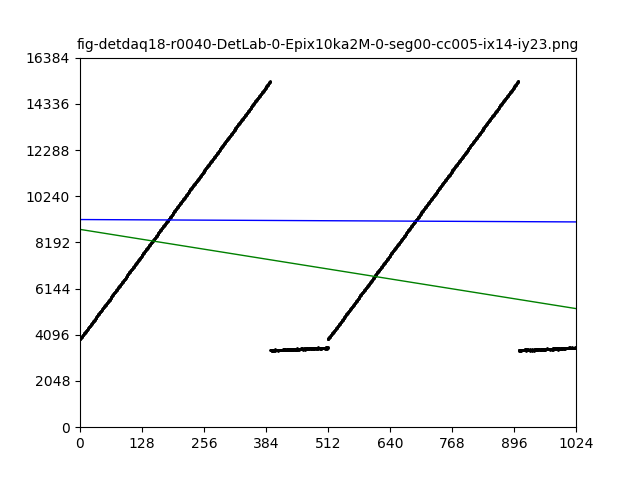
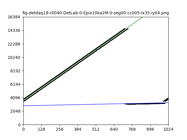
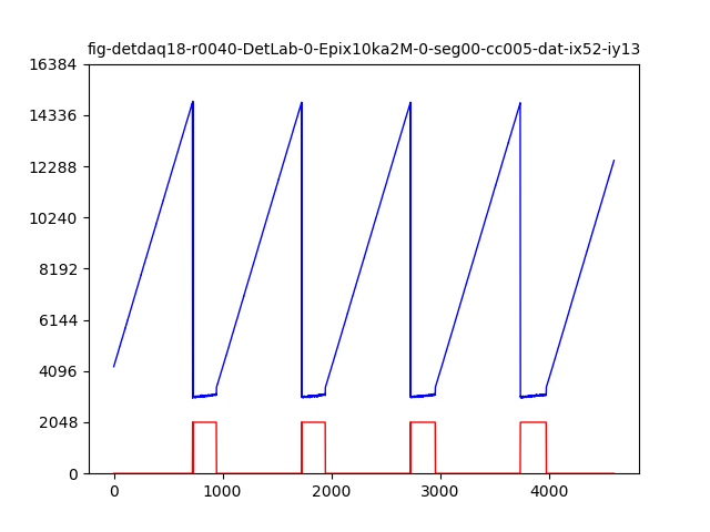
Left plots blue line is raw pixel intensity vs event number, red line - gain bit 14 status.
Right plots - associated fits. When fitted lines go close to dots it is ok, and vice versa.
It looks like gain factor for pixels might have spread x2 or so.
There is a few questions:
is it possible that in the same gain range pixel-channels have x2 different gain or something wrong with config or readout?
I do not quite understand algorithm how saw pulse generator works. Could you explain me please,
- when it starts cycle,
- when it resets,
- how long it does not inject charge in the beginning of cycle,
- (bonus question) how to find charge/voltage increment?
Mikhail
===============
Kwiatkowski, Maciej Thu 6/11/2020 10:00 AM
To: Dubrovin, Mikhail; Blaj, Gabriel
Hi Mikhail,
I think I have an answer for your question 1. It looks like the upper plot was taken without the ghost effect correction. Was it recorded in the past with the old firmware and the lower plots with the new one? To explain why this happens I will have to answer partially to your question 2. I'm sure the gain is the same in both cases.
The ASIC's test charge injection circuit uses a built in DAC that is incremented every frame until it rolls over and starts from 0V. The DAC is 10 bit so there is 1024 steps. This matches the upper plot.
The ghost correction algorithm was added to the firmware. It is to clear any remaining charge that leaks to the following frame. The firmware is just taking a dummy frame in between standard frames that you read out. The dummy frames are dropped and they never reach the DAQ. It has an effect on the ASIC's test circuit as also the dummy frame increments the built in DAC. Therefore with the latest firmware there is 512 DAC steps with doubled voltage increase and this matches to the lower plots that you sent. You will have to fix the fitter for the new firmware.
There is an ASIC register to reset the DAC if you want to always start from 0. Otherwise the cycle will start from where it was left last time. This is one bit register called PulserR that you should toggle True->False. I'm not sure if this was renamed in the DAQ so might not be exactly the same name.
Unfortunately I don't know what is the DAC voltage range and what is the cap value to convert this to charge. Either Angelo or Gabriel may know the answer.
Don't hesitate to ask if something of the above length email is not clear.
Best,
Maciej
|
2020-06-18 Calibration procedure for pedestals using charge injection
Reconstruction of data in analysis
<calibrated-data> = (<raw-data> - pedestal) * <gain-factor>
where pedestals and <gain-factor> are per-pixel map combined from 7 gain mode maps.
Calibration procedure
Accumulate dark data and evaluate pedestal for five gain modes:
- 5 calib-cycles: FH, FM, FL, AHL-H, AML-M (gain is not switching in dark)
and 2x49 charge injection samples (see plots) where gain is switching: - 7X7 calib-cycles: AHL
- 7X7 calib-cycles: AML
In charge injection samples each pixel has data and fit results as shown on plots.
Assuming that each gain mode intensity sample is parametrized as
<intensity> = B + <charge-index> * G
each pixel has constants like
- offset_AHL-L, offset_AHL-H, and evaluate their difference offset_ahl = H-L
- offset_AML-L, offset_AML-M, and evaluate their difference offset_aml = M-L
Then, in current calibration procedure we evaluate pedestal for two leftover gain modes AHL-L, AML-L as
- pedestal_AHL-L = pedestal_AHL-H - offset_ahl
- pedestal_AML-L = pedestal_AML-H - offset_aml


Panel results
detdaq18 run 52
Panel 2(counting from 0) /reg/g/psdm/detector/gains/epix10k/panels/0000000001-0175233793-0553648150-0743498629-0017156647-0000000000-0000000000
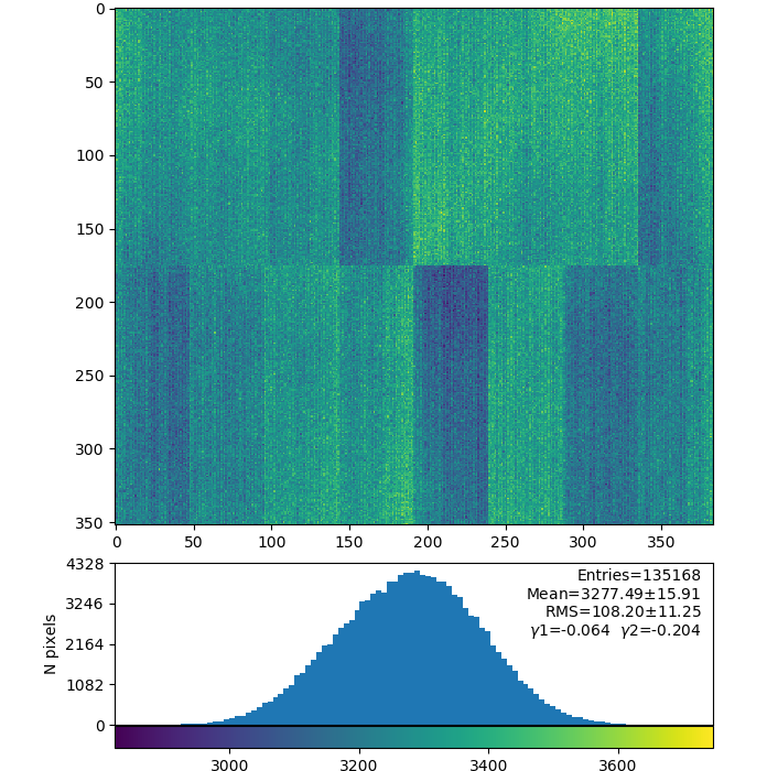
Pedestal for fixed gain modes FH, FM, FL


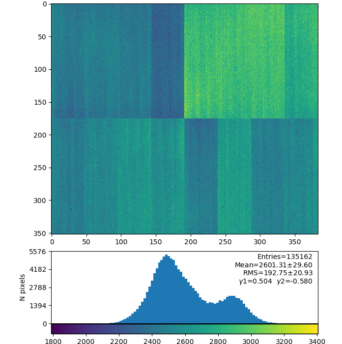
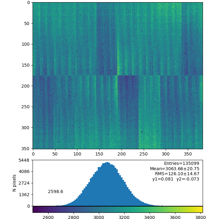
Pedestal for switching gain modes AHL-H and derived AHL-L AML-M and derived AML-L


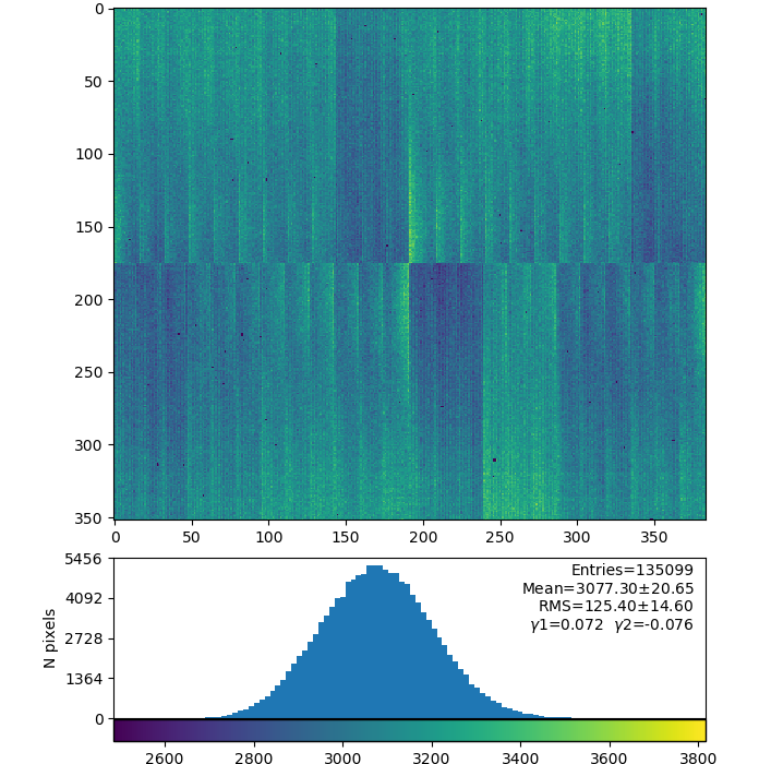
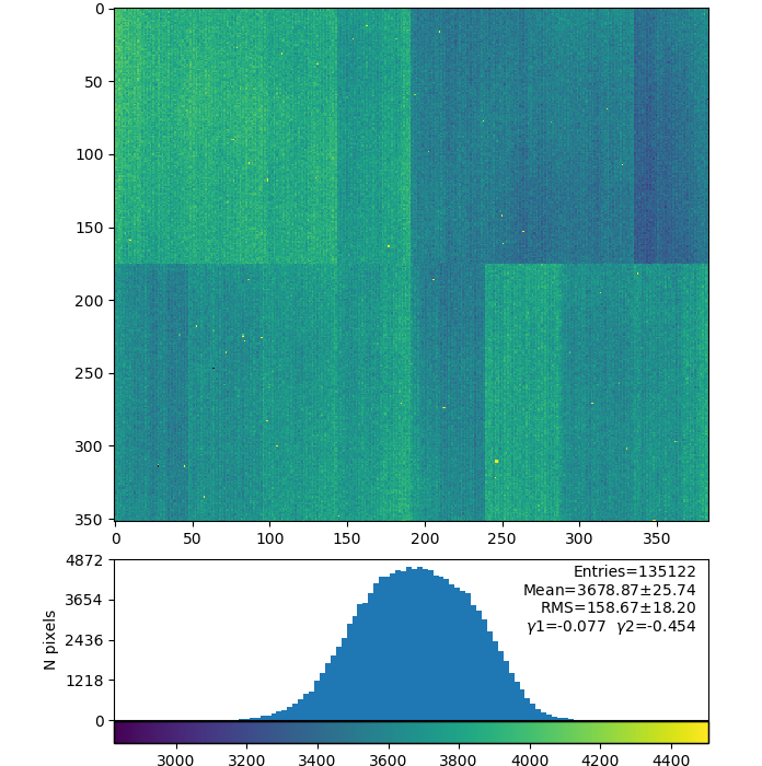
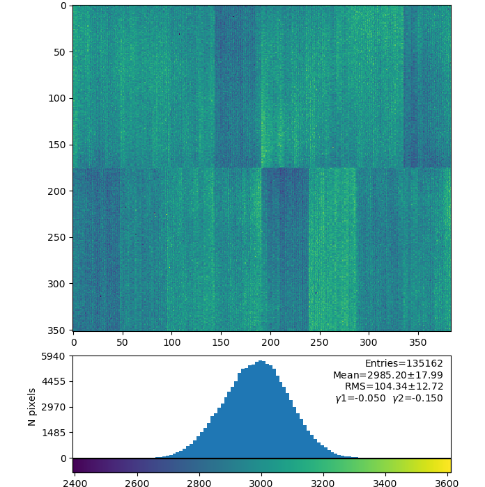
Offset (B) for switching gain modes AHL-H, AHL-L, AML-M, AML-L

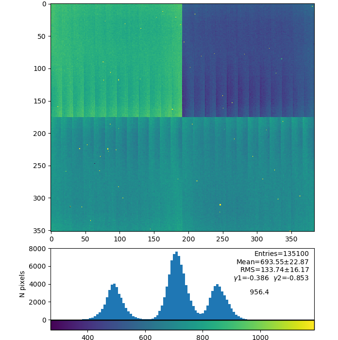
Offsets difference H(or M) - L for AHL, AML

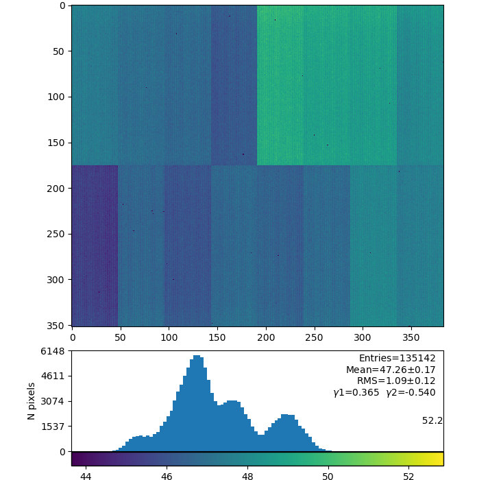
Gains (G) for switching gain modes AHL-H, AHL-L, AML-M, AML-L


Mean values
| Fixed gain mode | FH | FM | FL |
|---|---|---|---|
| pedestal | 3392 | 3293 | 3277 |
| Switching gain mode | AHL-H | AHL-L | AML-M | AML-L |
|---|---|---|---|---|
| pedestal H(M)-from dark, L-evaluated | 3332 | 1825 | 3295 | 2601 |
| offset (B) from fit | 4584 | 3077 | 3679 | 2985 |
| offset (B) difference H(M)-L | 1507 | 694 | ||
| gain (G) from fit | 47 | 0.52 | 15.4 | 0.49 |
Denote
- p - pedestal
- B - fit base-level offset parameter, <intensityADU> = B + G * <event-index-from-0-pulser>
- G - gain
Current (plots above and results in table) naive version of L-pedestals evaluation
- pL = pH - (BH-BL)
Gabriel's version
- pL = BL - (BH-pH)*GL/GH

L-pedestals using Gabriel's formulae for AHL-L and AML-L

Questions
- do we need to account for the difference between offset (B) and pedestal (Gabriel's version)
- the same difference may be between fit B(L) and pedestal(L) OR it is smaller due to the gain?
- is current procedure correct?
- if not
- what is correct procedure?
- or what could we calibrate with charge injection?
2020-06-22 ASIC issue
detdaq18 run 52
Panel 14 (counting from 0) /reg/g/psdm/detector/gains/epix10k/panels/0000000001-0175696641-1056964630-1010951301-0019435010-0000000000-0000000000
Data for a few charge injection points
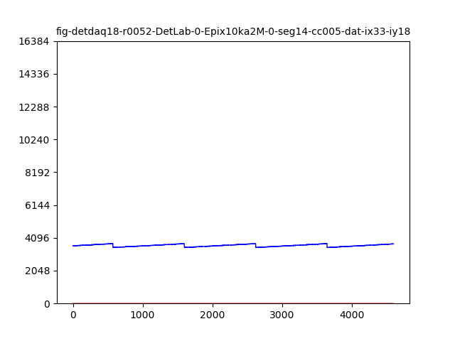


Injected charge or gain is too small to switch to L-gain mode...
Gains AHL-H, AHL-L, AML-M, AML-L


Panel 14(next-to-last) charge injection in ASIC1 does not work
2020-06-24 calibration constants for ALL gain ranges and panels
detdaq18 run 52
pL were evaluated using Gabriel's formulae.
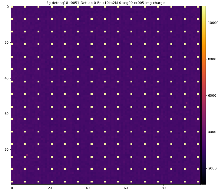
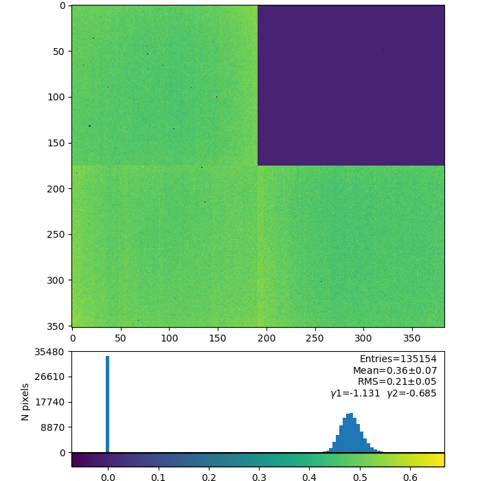
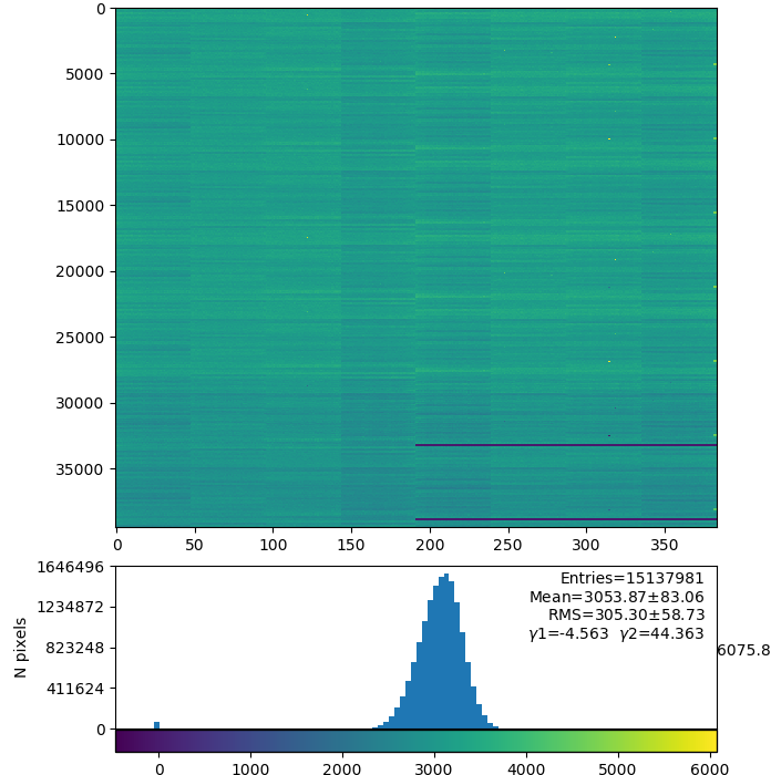
plots for pedestals, pixel_rms, pixel_status, pixel_gain (default), gain from charge injection
![]()
![]()
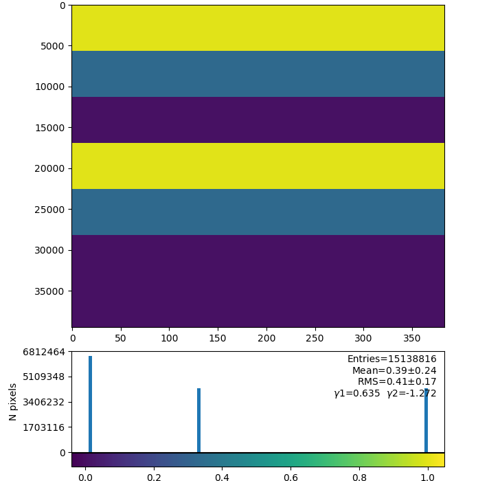

deployed as
/reg/d/psdm/det/detdaq18/calib/Epix10ka2M::CalibV1/DetLab.0:Epix10ka2M.0/*/52-end.data
SHAPE (7,16,352,384) : 7-gains, 16-panels of shape (352,384)
References
...
Overview
Content Tools