...
| Unit #2 Model | 10-400-3G20-1-CP2-R2-LT-AR |
|---|---|
| -400 | ~400W @ 20C with ambient air cooling for the Cube |
| 3G20 | >3 lpm @30 pig magnetic drive gear pump. Adjustable flow setting for 2 lpm. |
| CP2 | 3/8" CPC shut off valve (1-3 lpm) |
| R2 | RS232 interface controller |
| LT | Low temperature operation (<5C) |
| AR | Auto reset - software |
* product details: https://www.sscooling.com/product/thermocube-liquid-to-liquid/
*manual: https://www.sscooling.com/wp-content/uploads/2021/07/ThermoCube-Liq-Liq-Manual-Rev-M13.pdf
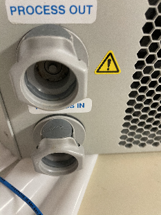
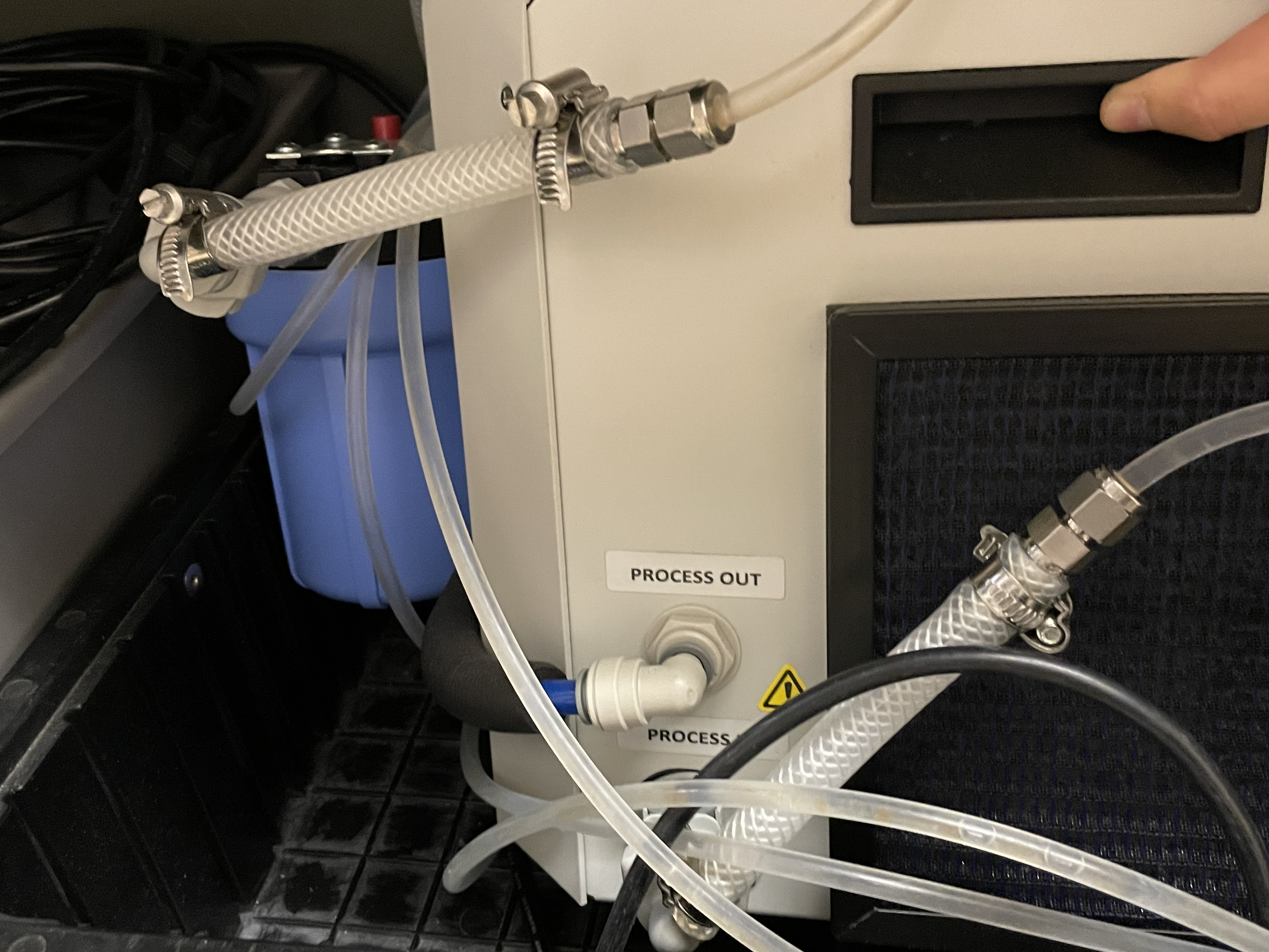
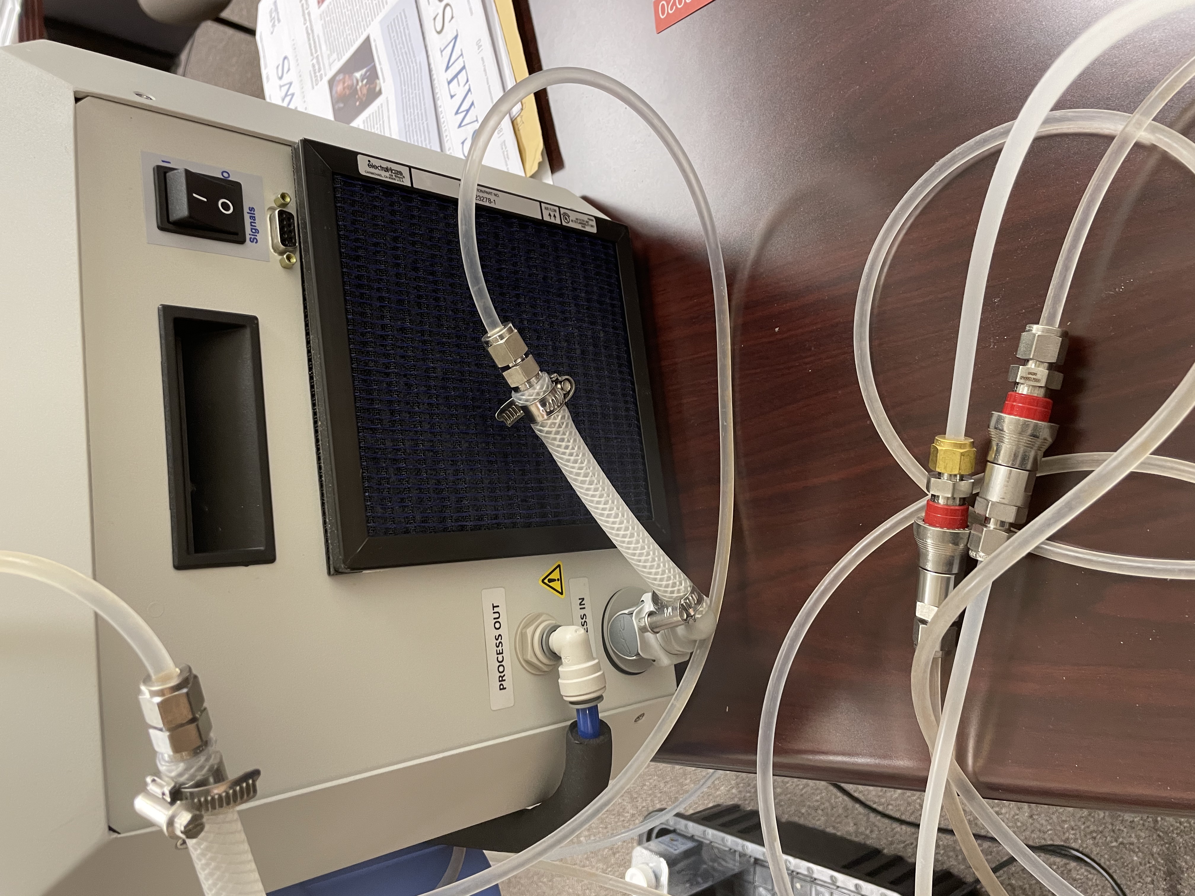
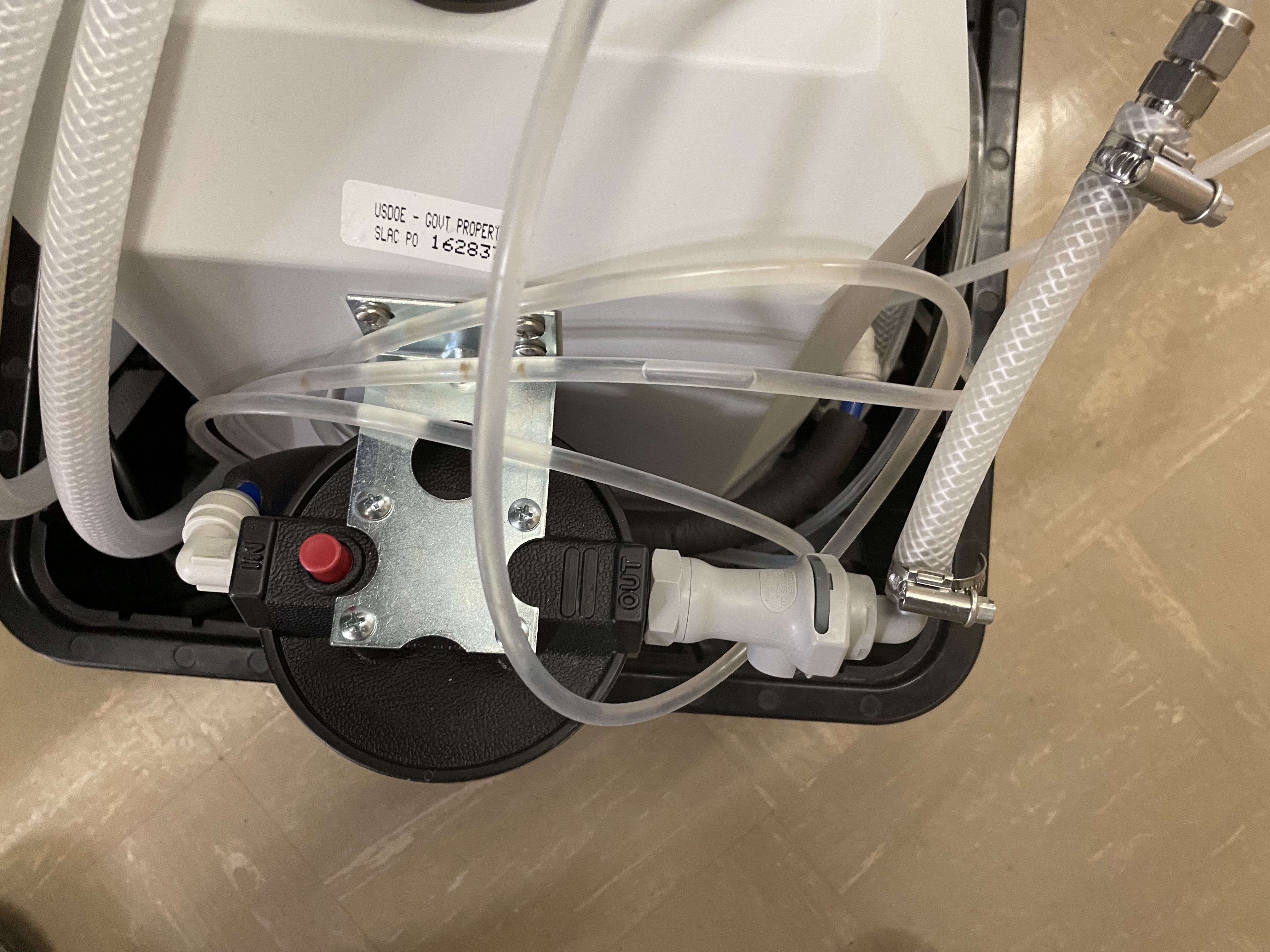
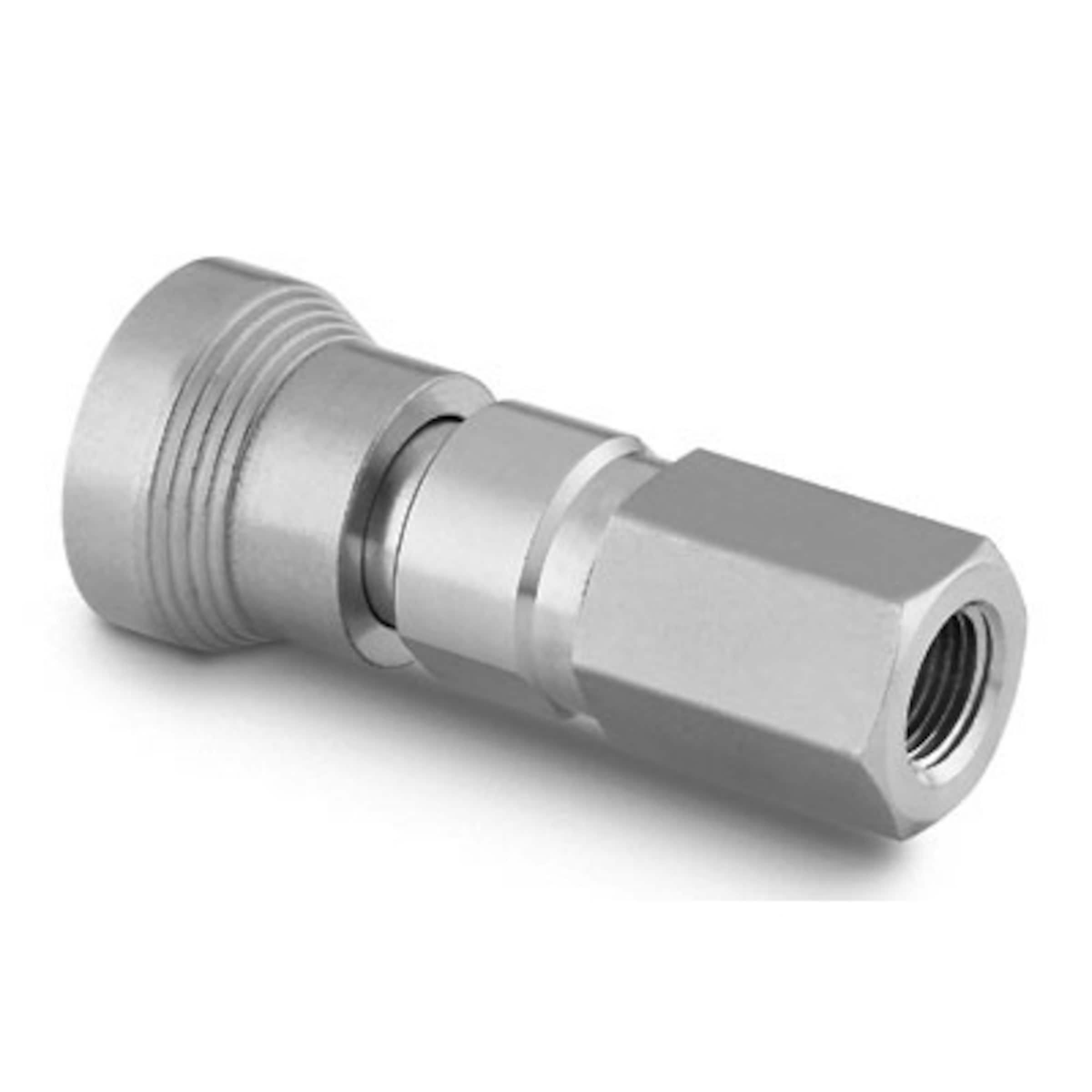
| Coolant connector (3/8" CPC) on unit #2 | Connection to the filter for unit #1 | Unit #1 with Swagelock QC4-316 joint for application insertion | Unit #1 view from above its filter |
|---|---|---|---|
| |
|
|
...
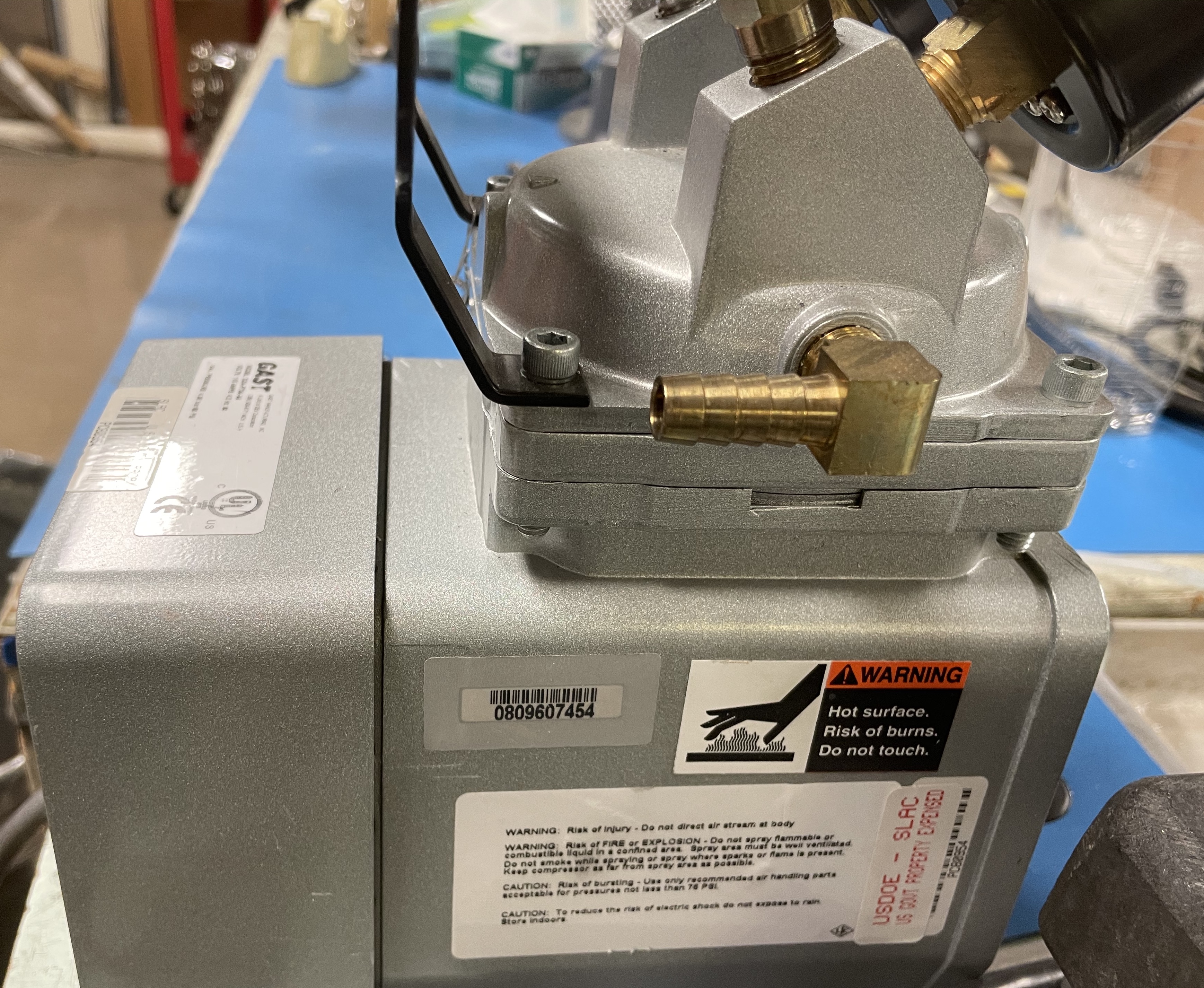
Table for vacuum unit connections
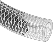
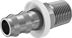
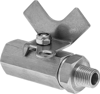
| Left pump port with 3/8" barb | High-Pressure Firm Polyurethane Rubber TubingID:OD=3/8":5/8" Link ~1.5 m | 316 Stainless Steel Push-on Hose Fitting for Air and Water3/8" Hose ID, 1/4 NPT Male End Link | On/off valve High-Pressure Compact 316 Stainless Steel On/Off Valvewith lock-able T-handle, 1/4 NPT Female x 1/4 NPT Male | 1/4" Tee316 Stainless Steel Threaded Pipe FittingLow-Pressure, Tee Connector, 1/4 NPT Female |
|---|
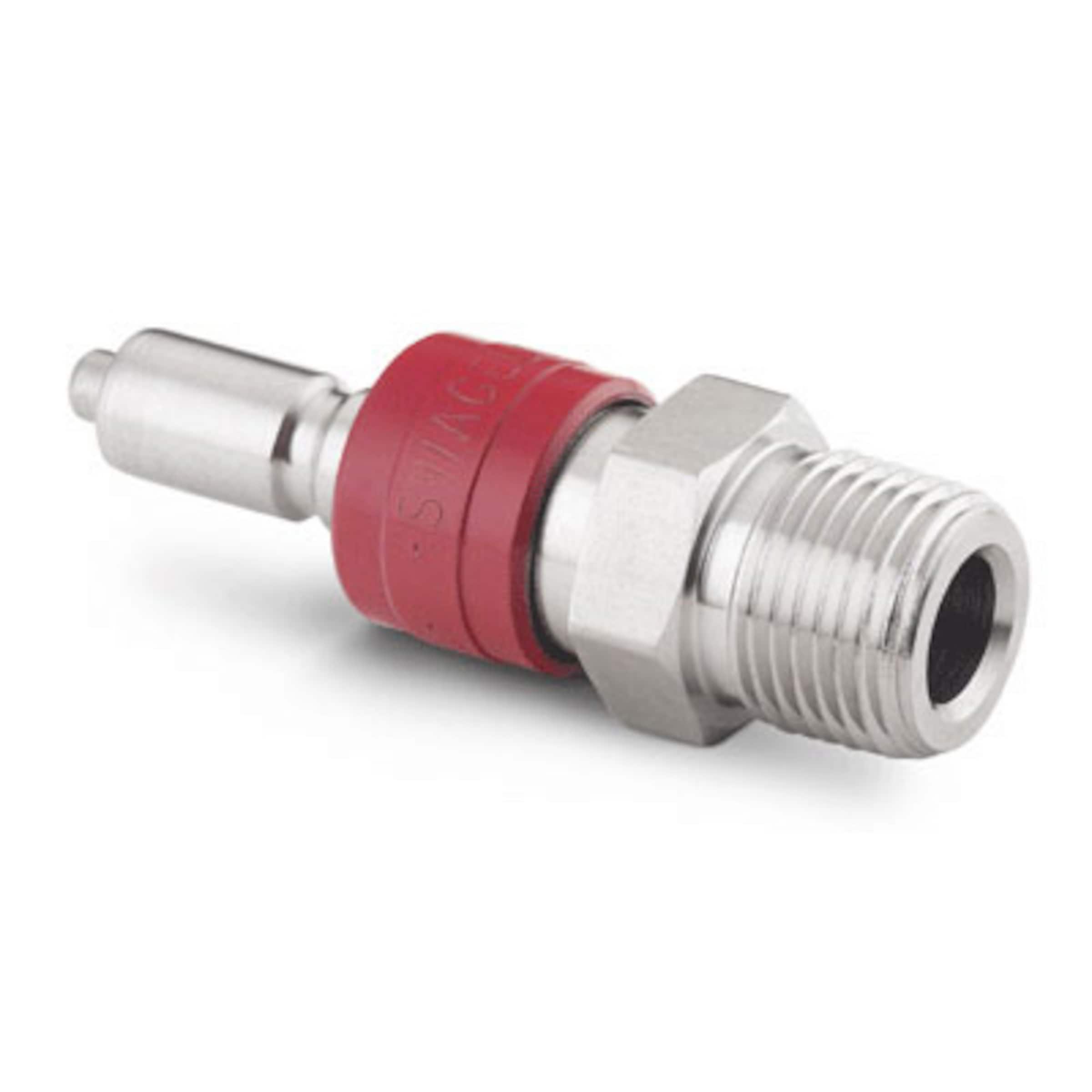
Stainless Steel Instrumentation Quick Connect Stem with Valve, 0.2 Cv, 1/4 in. Male NPT SS-QC4-D-4PM | Stainless Steel Instrumentation Quick Connect Body, 0.2 Cv, 1/4 in. Female NPT SS-QC4-B-4PF | Plastic Barbed Tube Fitting for Air and WaterSwivel Adapter, for 1/16" Tube ID (1.6 mm)x 1/4 NPT Male | cern tube OD/ID=3mm/1.8mm (~30cm) | |||||
|---|---|---|---|---|---|---|---|---|
|
|
| (replacing original unavailable part) |
|
|
|  |

Dry Air
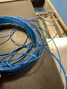
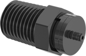
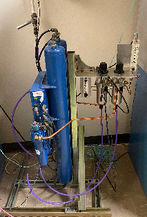
| The dry air filters were saved by Matt from BaBar, residing inside the curtained area of B84 EPP lab. House compressed air are filtered to let out through the flow meter with a max flow of 20 ft3/min. A 80ft long hard polypropylene tubing with 1/4" OD (McMaster-Carr #9349T2) takes the drive air down to the ATLAS benches. The dry air supply tube terminates at a diverting valve (no shutoff) (McMaster #45165K42) on the bench to allow the switching of the dry air between a test port and the through path to module cooling unit. The through path continues with the same type of tube to transition to the 30cm long dry air tube into the module cooling unit which is an ID/OD=1.8mm/3.0mm blue tube from CERN shipment (same as the vacuum tube). This transition uses a pair of Aluminum low-pressure 1/4 NPT adaptor to barbed tube fitting: 1/4" barb - male NPT (with O-ring) on supply side (McMaster-Carr #5058K441); 1/16" barb and female NPT on module side (McMaster-Carr #5058K641). The initial turn on of dry air should let run for a few hours with the outlet going to the test port using the diverting valve. Check flow and humidity at the test port before flowing into the module cooling unit. Once on for operation, the dry air flow should not be turned off. From an off state, the restart should always have the few hours of initial flush first. During operations, if the dry air needs to be off at the module cooling unit, use the diverting valve to temporarily directing the air to the test port. |
|---|
...
Tests with cooling setting: https://drive.google.com/file/d/1erEyUlxmHoDTqO4uOqtkao5QjmEfbS6A/view?usp=sharing (updated with test done on 06.07.2021)
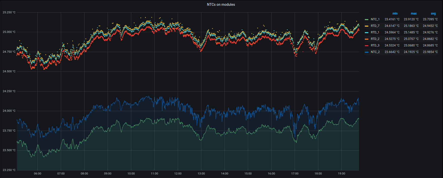
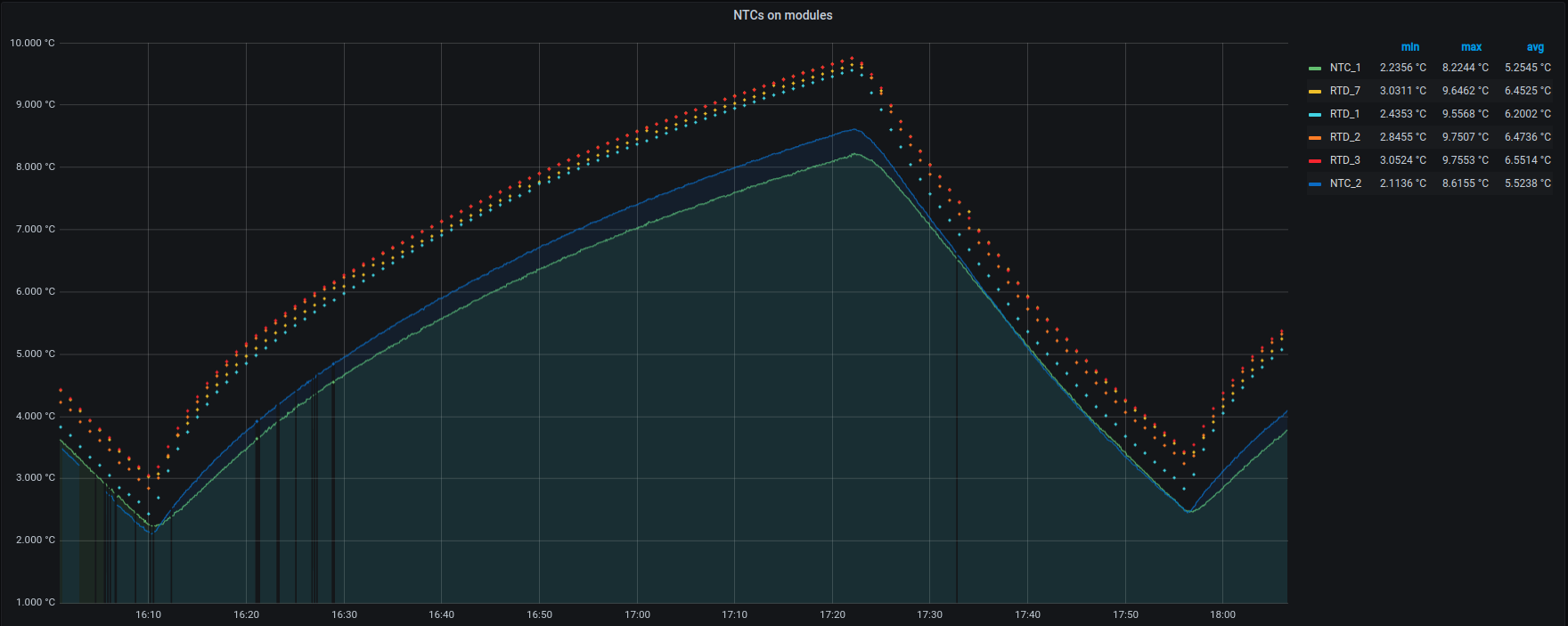
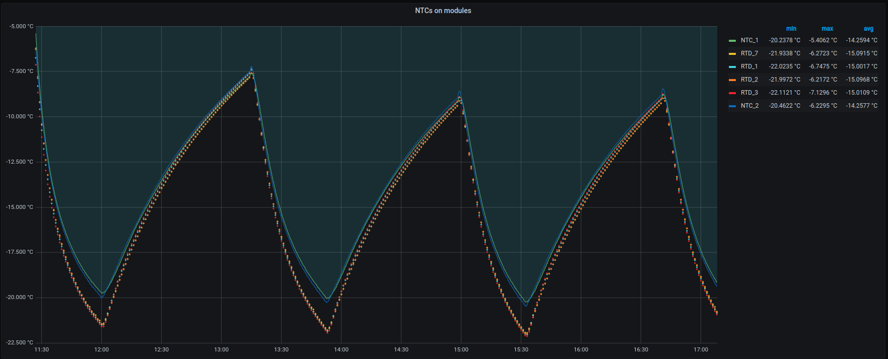
Temperature Agreements:
Tests where done to see if the NTC and RTD temperature data was consistent at or near operating temperatures. As can be seen there is a drift where the RTD reads 2 ℃ lower then the NTC. However at room temperature this difference is reversed and reads about 1 ℃ higher.
| Name in results | Sensor, Location | Accuracy | DataSheet |
|---|---|---|---|
NTC_1 | NTCG103JF103FTDS, On RD53A | ±.5 ℃ | https://product.tdk.com/system/files/dam/doc/product/sensor/ntc/chip-ntc-thermistor/catalog/tpd_automotive_ntc-thermistor_ntcg_en.pdf |
| NTC_2 | 192-103LEW-A01, Taped to mounting plate of RD53A | ±1℃ | https://www.mouser.com/ProductDetail/Honeywell/192-103LEW-A01?qs=F1jq4PciTHu1X2%252BS%2F4fB2A%3D%3D |
| RTD_7 | pT100, Taped to mounting plate of RD53A | ±.15 ℃ | https://www.mouser.com/ProductDetail/Heraeus-Nexensos/32208550?qs=MQgg6%252BVqoaOPAnuE2NwxiQ%3D%3D |
| RTD_1 | pT100, Taped to mounting plate of RD53A | ±.15 ℃ | https://www.mouser.com/ProductDetail/Heraeus-Nexensos/32208550?qs=MQgg6%252BVqoaOPAnuE2NwxiQ%3D%3D |
| RTD_2 | pT100, Taped to mounting plate of RD53A | ±.15 ℃ | https://www.mouser.com/ProductDetail/Heraeus-Nexensos/32208550?qs=MQgg6%252BVqoaOPAnuE2NwxiQ%3D%3D |
| RDT_3 | pT100, Taped to mounting plate of RD53A | ±.15 ℃ | https://www.mouser.com/ProductDetail/Heraeus-Nexensos/32208550?qs=MQgg6%252BVqoaOPAnuE2NwxiQ%3D%3D |
| Room temperature, no load on module | In fridge, no load on module | In freezer, no load on module. |
 |
|
|
The NTC on the modules are type NTCG103JF103FTDS. More information about these modules can be found at https://twiki.cern.ch/twiki/bin/view/Atlas/ItkPixModuleTesting#Reading_out_the_NTC_Module.
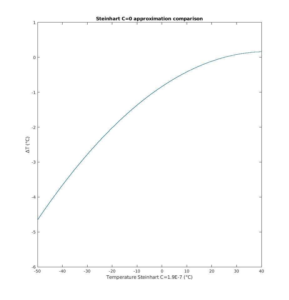
However the data sheet and the twiki about the sensors do not agree about the relationship between the resistivity and temperature. The differences is plotted below. Note Δt is the Data Sheet value minus the twiki results. In all our code the temperature is calculated via the data sheet values.
| Latex |
|---|
\begin{equation}
\frac{1}{T} = \frac{1}{B} Log(\frac{R}{R_0}) + \frac{1}{T_0}
\end{equation} |
With B = 3380, R0 = 10,000 Ohms and T0 = 25℃