Naming Conventions for Control System Devices
Note : this document is currently being updated. Notably, the examples are not yet finalized.
...
| Panel |
|---|
Devices are named with a sequence of characters in the following format: | Wiki Markup |
|---|
{center}{*}DeviceType* : *Area* : *Position{*}{center} |
An example of a device name looks like this: | Wiki Markup |
|---|
{center}{*}QUAD* : *IN20* : *122* {center} |
There are functions and parameters associated with devices, which also need to be identified. An Attribute field provides that information: | Wiki Markup |
|---|
{center}{*}DeviceType* : *Area* : *Position* : *Attribute* {center} |
unmigrated-wiki-markupThe _DeviceType_ and _Position_ fields also have optional characters. We can denote optional symbols with *\[* and *\]*, so the names can be described as: | Wiki Markup |
|---|
{center}*\[* DeviceType *\]* *DeviceDetail* : *Area *: *\[* PositionPrefix *\]* *Position* : *Attribute* {center} |
To summarize: - A Device is named by 3 fields, separated by 2 colons.
- A function or parameter of a device, known internally to the Control System as a Process Variable (PV) is named by the 3-field device name followed by another colon, and the Attribute field.
|
...
- All fields are required to be Upper Case characters the the exception of the Attribute field which is allowed to be mixed case with the following constraints.
- There must be zero requirements for access to the PV from the SLC Control System (SCP). The SLC Control System is case insensitive and will be unable to read the mixed case PVs.
- Is it strongly suggested that UpperCamelCase* be used for mixed case, however all uppercase still should be used as much as possible when creating new PV names. We realize that when we bring in support from other labs, the case may have a different format, but all PVs names that we create should either be all upper case or UpperCamelCase .
- The attribute part of the name is the only part that is allowed to have mixed case, device, area, and unit number fields are still required to be all upper case.
- It is not allowed to have different PVs which only differ in case.
- The entire name is currently restricted to 28 characters or less.
- The DeviceType is between 3 and 9 characters in length. The generic type of device is denoted by 3 or 4 characters, and may optionally be followed by an underscore with 3 or 4 more characters to indicate details of that device.
- The Area field is 4 characters in length, and describes one of the 21 areas currently in the LCLS Accelerator.
- The Position field can be up to 4 characters in length, which includes either an optional 1-character position prefix followed by 3 digits (for devices associated with the beam line) or 2-character prefix followed by an index for non-beam-line devices which are itemized.
- The Attribute field must be 12 characters or less.
- All PV names must be unique in the control system. This includes being unique across machines such as LCLS, SLC, FACET, FACET-II, and LCLS-II.
The optional fields are meant to accommodate the SLC-Aware IOC mechanism, which has even more restrictions placed on Device names. For more information, from the original Naming Convention plans, click here.
...
The following table lists magnet and magnet power supply Compound DeviceTypes:
Table 1.0 |
|---|
Value | Device Type |
|---|
SLC-Aware | Controllable |
|---|
BEND | Bend (Large Dipole) Magnet |
Y | Y |
BTRM | Bend Magnet Trim Windings |
Y N | N | QTRM | Quad Magnet Trim Windings | Y |
Y | Y | Y | Y |
XCOR | Horizontal Steering Corrector Magnet |
Y | Y |
YCOR | Vertical Steering Corrector Magnet | Y |
USEG | Undulator Magnet Segment | Y |
WIGG | Wiggler Magnet | Y |
The following is a list of power supplies
Table 1.0.1 |
|---|
Value | Device Type |
|---|
SLC-Aware | Controllable |
|---|
HVPS | High Voltage Power Supply | Y |
Y | Y N The following table lists RF system Compound DeviceTypes:
Table 1.1 |
|---|
Value | Device Type |
|---|
SLC-Aware | Controllable |
|---|
ACCL | Accelerating Section |
N | N | N | N | Y |
TCAV | Transverse Deflecting Cavity |
N | Y |
REFS | Machine Parameters Set Points |
N
| | | The following table lists vacuum Compound DeviceTypes:
Table 1.2 |
|---|
Value | Device Type |
|---|
SLC-Aware | Controllable |
|---|
VGBA | Vacuum Gauge Baratron |
N | N |
VGCM | Vacuum Capacitance Manometer |
N | Y |
VGKL | Vacuum Gauge associated with a Klystron | N |
N | N | N |
VGCC | Vacuum Cold Cathode Gauge |
N | Y |
VGEX | Vacuum Extractor Gauge | Y |
VGTC | Vacuum ThermoCouple Gauge |
N | N |
VGCP | Vacuum Convection-enhanced Pirani Gauge |
N | N |
VGHF | Vacuum Hot Filament Gauge |
N | Y |
VGOS | Vacuum Overpressure Switch | N |
N | VGXX | Combination Vacuum Gauge | N |
N | VVKL | Vacuum Valve associated with a Klystron |
N | Y |
VVPG | Vacuum Pneumatic Gate Valve |
N | Y |
VVMG | Vacuum Manual Gate Valve |
N | N |
VVPR | Vacuum Pneumatic Roughing Valve |
N | Y |
VVMR | Vacuum Manual Roughing Valve | N |
N | VVPF | Vacuum Pneumatic Fore Valve |
N | Y |
VVMF | Vacuum Manual Fore Valve | N |
N | VVPV | Vacuum Pneumatic Vent Valve |
N | Y |
VVMV | Vacuum Manual Vent Valve | N |
N | () Valve N | Y |
VVFV | Vacuum Valve Fast Valve | Y |
VVFL | Vacuum (Mass) Flow Valve |
N | Y |
VPKL | Vacuum Pump associated with a Klystron |
N N CRyo N | N | N | N VPFO Fore Vacuum Pump NEG Ion Combination |
N | VPRO Roughing Pump | N | Y | VRGA
| Residual Gas Analyzer | N
| | Y | |
Vacuum Pump NEG (Non-Evaporable Getter) | sometimes Y
|
VPFO | Fore Pump | Y |
VPRO | Roughing Pump | Y |
The following table lists system Compound DeviceTypes:
Table 1.3 |
|---|
Value | Device Type |
|---|
SLC-Aware | Controllable |
|---|
AIR | Compressed Air System for Pneumatic Control | N |
AMS | Air Monitoring System for measuring radiation levels from intake samples | N |
NITR | Process Nitrogen Gas for Attenuator/Detector |
N | Y |
ARGO | Process Argon Gas for Attenuator/Detector |
N | Y |
BCS | Beam Containment System | N |
N | HVAC | Heating, Ventilation, and AC System | N |
N | N N | MPS | MPS (Machine Protection System) | N |
N | PPS | PPS (Personel Protection System) | N |
N | The following table lists Compound DeviceTypes for beam synchronous acquisition:
Table 1.4 |
|---|
Value | Device Type |
|---|
SLC-Aware | Controllable |
|---|
ARRY | Group of BSA Channels for SLC-Aware only |
Y | N |
APD | Avalanche Photo Diode | N |
N | Y | N |
BPMS | Beam Position Monitor |
Y | N |
CAMR | Camera for Optics and Beam Profile |
N | N | N |
FARC | Faraday Cup | N |
FREQ | Frequency Counter | N |
JMTR | Joule Meter (for Laser) | N |
N | MDEF | SLC Measurement Definition | Y |
Y | EDEF | EPICS Event Measurement Definition |
N | N N | N | Y |
PMT | Photo Multiplier Tube |
N Y N | N | WPM | Wire Position Monitor | N |
N | The following table lists other Compound DeviceTypes:
Table 1.5 |
|---|
Value | Device Type |
|---|
SLC-Aware | Controllable |
|---|
APC | All Purpose Controller (e.g. Beckhoff raw signals) |
N N | N | N | N | N N ECAT | Ethercat | Y |
EXPT | Experiment |
N | N Y FOIL | Diagnostic Foils
| Faraday Cup | N |
FREQ | Frequency Counter | N |
FOIL | Diagnostic Foils, Slotted Foil |
N N | N N | Y |
HLS | Hydrostatic Leveling Sensor | N |
N | N | N | N | LVDT | Linear Variable Differential Transformer | N |
N | N N | Y |
PICS | Protection Ion Chamber Signal | N |
N | PICM | MPS Protection Ion Chamber Signal |
N | N |
PLIC | Panofsky Long Ion Chamber |
N | N |
PKLS | Pockels Cell (photon attenuation) | Y |
RADF | RADFET (radiation dose sensor) |
N | Y |
RADM | Radiation dose sensor | Y |
ROOM | Room, vault, or tunnel | N |
N | RTD | Resistive temperature detector |
N N | N Y |
SBI | Sub-Booster Interface Chassis | Y |
SHUT | Shutter (mechanical, optical shutter) |
N | Y |
SLIT | Slit (mechanical, 2- or 4-jaw) |
N | N | Y N N | N | N | Y |
UTIC | Universal Time Interval Counter |
N | Y |
TIU | Tone Interrupt Unit (for MPS) |
N N | N | Y |
XTAL | Crystal Monochromator |
N | N | N The following table lists what are currently considered Component DeviceTypes that are either controllers or control modules:
Table 1.6 |
|---|
Value | Device Type | Controllable |
|---|
PSC | PS EIOC | Embedded Input/Output Controller | Y |
IOC Input/Output MOC Motor MCOR Controller | Y |
PAC | Phase and Amplitude Controller | Y |
PLC | Programmable Logic Controller | Y |
PSC | Ethernet PS Controller | Y |
VGC | Vacuum Gauge Controller | Y |
VPC | Vacuum Pump Controller | Y |
VVC | Vacuum Valve Controller | Y |
VFC | Vacuum Flow Controller | Y |
The following table lists Component DeviceTypes for control system modules and instruments:
Table 1.7 |
|---|
Value | Device Type |
|---|
SLC-Aware | Controllable |
|---|
ADC | Analog-to-Digital Conversion Module |
N | N |
AFG | Arbitrary Function Generator |
N | Y |
DAC | Digital-to-Analog Conversion Module |
N | Y |
BPMP | Beam Position Module |
Y | N | CHAS | Input/Output chassis | N |
N | CRAT | Input/Output (VME) Crate | Y |
CV | CrateVerifier Module (CAMAC) | Y |
DI | Digital Input Module | N |
N | N | DIO | Digital Input/Output Module | N |
N | N | N N | EVG | IDIM | 16-bit Digital Input Module (CAMAC) | Y |
IDOM | 16-bit Digital Ouput Module (CAMAC) | Y |
LDIM | 32-bit Digital Input Module (CAMAC) | Y |
EVG | Event Generator for Timing |
N | Y |
EVR | Event Receiver for Timing |
Y | Y | MCOR | MCOR for Magnet PS | N N | Y |
MPG | Master Pattern Generator |
N | Y |
PAD | Phase and Amplitude Detector | N |
N | N Module (CAMAC) | Y |
PMTR | Power Meter |
N | Y |
PMGR | Power Management Module |
N | PSC | Ethernet Power Supply Controller | N | Y |
N | SAM | SmartAnalog Module (CAMAC) | Y |
N | N | SCOP | Oscilloscope Y N The following table lists Component DeviceTypes for the network:
Table 1.8 |
|---|
Value | Device Type | Controllable |
|---|
ACSW | AC Switch | Y |
CSWH | aTCA Carrier Switch | Y |
GPIB | GPIB/LAN Gateway | Y |
RTR | Router | N |
SWH | Ethernet Switch | N |
SCOP | Scope | N |
TS | Terminal Server | Y |
UPS | Uninterruptible Power Supply | N |
WKUP | Walk-up ethernet connection | N |
ICS | Intercom System | N |
IOC | EPICS IOC | Y |
PLC | Programmable Logic Controller | Y |
PNA | Phase Noise Analyzer | Y |
PSC | Power Supply Controller | Y |
CAMR | Camera for Beam Line Optics | Y |
CRAT | Intelligent VME Crates | Y |
PC | Computer that is not an IOC | Y |
WB | Wireless Bridge | N |
Certain parameters or functions associated with a component device might be accessible from the compound device. For example, we might consider a water flow value as an independent, measurable quantity associated with a water line; it might be a transducer which produces pulses which are connected to a computer-readable counter. That value might be retrieved using a name like SCLR : IN20 : K701 : COUNT which indicates a scaler module in a VME crate in the klystron gallery at sector 20.
However, if the water is being used to dissipate heat from a Faraday Cup, then one would retrieve a value using a name like FARC : IN20 : IS998 : FLOW, which is a value based on the scaler measurement described above. The scaler must be accessible on its own since it might have some built-in diagnostic tests that are required for maintenance. The compound device will typically give the component's measurement in more appropriate engineering units.
...
The optional characters that come after the underscore provide detail. The following table lists the Detail Codes associated with specific device types.
Table 1.9 |
|---|
DeviceType Name | Purpose |
|---|
ADC_SCAN | Scanning ADC |
ADC_PEAK | Peak-sensing ADC |
ADC_CHRG | Charge Integrating ADC |
The Area Field
The Area field is 4 characters in length. The following diagram and table lists the approved area names. A larger version of the diagram, can be found at the end of this page.
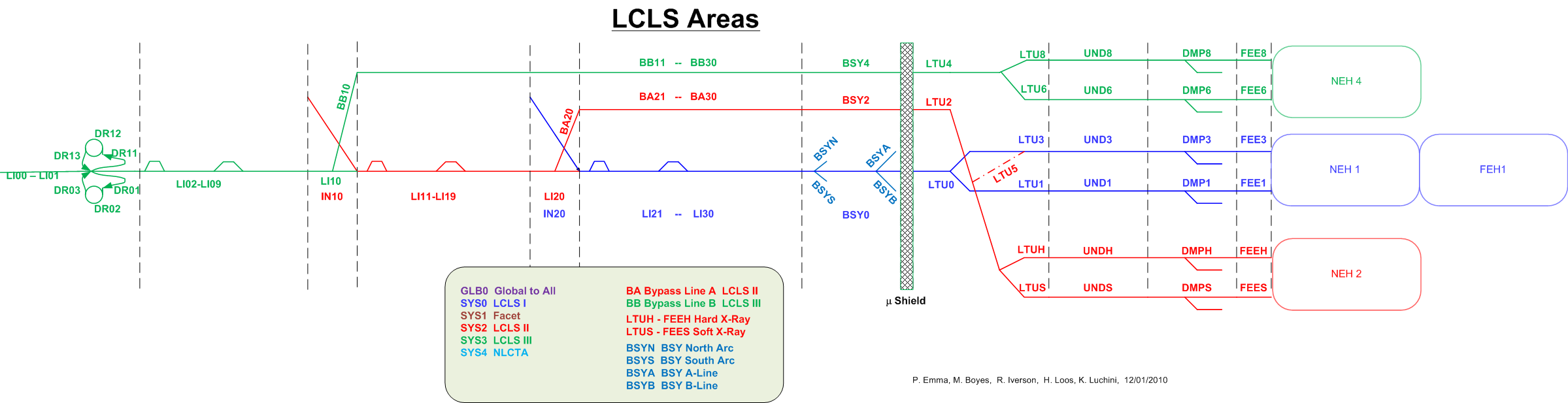
Table 1.10 |
|
|---|
Area | Physical Location |
|---|
Access Buildings |
AS01 Test System LI00 | LINAC Sector 0 |
LR20 | Laser Room (Upstairs, near sector 20) |
IN20 | Injector |
LI20 | LINAC Sector 20 |
LI21 | LINAC Sector 21 |
LI22 | LINAC Sector 22 |
LI23 | LINAC Sector 23 |
LI24 | LINAC Sector 24 |
LI25 | LINAC Sector 25 |
LI26 | LINAC Sector 26 |
LI27 | LINAC Sector 27 |
LI28 | LINAC Sector 28 |
Control Room (B052) |
B005 | Building 5 |
B24 | Building 24 (development) |
B25 | Building 25 (development) |
B34 | Building 34 (development) |
B44 | Building 44 - Klystron Test Lab |
B81 | Building 81 - MMF |
B106 | Building 106 |
B106 | Building 136 |
B911 | Building 911 |
B911 | Building 911 |
B911 | Building 911 |
B921 | Building 921 |
ASTA-UED Facility Area |
AS01 | Accelerator Structure Test System |
Injector Machine Areas |
LR10 | FACET-II Laser Room (Upstairs, near sector 10) |
LR20 | LCLS Laser Room (Upstairs, near sector 20) |
LA20 | FACET Laser Room (Upstairs, near Sector 20) |
IN10 | FACET-II Injector |
IN20 | LCLS Injector |
LINAC Areas |
LI00 | LINAC Sector 0 |
LI20 | LINAC Sector 20 |
LI21 | LINAC Sector 21 |
LI22 | LINAC Sector 22 |
LI23 | LINAC Sector 23 |
LI24 | LINAC Sector 24 |
LI25 | LINAC Sector 25 |
LI26 | LINAC Sector 26 |
LI27 | LINAC Sector 27 |
LI28 | LINAC Sector 28 |
LI29 | LINAC Sector 29 |
LI30 | LINAC Sector 30 |
Beam Switch Yard |
For the entire beam switch yard area spanning from the wooden door to the Muon Shield, the device positions shall range from 100-999, consistently across all beam lines, such that the unit numbers match up in Z-position across all beam lines. |
LI29 | LINAC Sector 29 |
LI30 | LINAC Sector 30 |
MCC0 | Main Control Center ( |
Bulding 005) B005) OBSOLETE. Replaced with ACR0 |
CLTH | Copper LINAC to Hard Line |
CLTS | Copper LINAC to Soft Line |
BSYH | Beam Switch Yard Hard Line |
BSYS | Beam Switch Yard Soft Line |
BSY0 | Beam Switchyard Common-line |
BSYN | Beam Switchyard North Arc |
BSYS | Beam Switchyard South Arc Switchyard line ESA0 | End Station A and Beam Dump East |
BSYB | Line |
SLTH | Superconducting LINAC to Hard Line |
SLTS | Superconducting LINAC to Soft Line |
SLTD | Superconducting LINAC to Dump Line |
BSYS | Beam Switch Yard South Arc |
LINAC to Undulator Machine Areas |
Beam Switchyard B-line Undulator Switchyard Undulator directly after BSY |
LTU1 | LINAC-to-Undulator Line 1 |
Undulator |
UND1 | Undulator on Line 1 |
Dump |
DMP1 | Beam Dump on Line 1 |
Photon Areas |
FEE1 | Front End Enclosure on Line 1 |
NEH1 | Near Experimental Hall on Line 1 |
XRT1 | X-Ray Tunnel on Line 1 |
FEH1 | Far Experimental Hall on Line 1 |
XTA Facility Area |
XT01 | X-Band Test Area |
Global Areas |
SYS0 | LCLS-I System |
SYS1 | FACET and FACET-II System |
SYS2 | LCLS-II System |
SYS3 | LCLS-III System |
SYS4 | NLCTA System |
SYS5 | SPEAR Systems |
SYS6 | X-Band |
Test Area SYS7 | ASTA Test Area Test Area |
SYS7 | ASTA Test Area |
SYS8 | Klystron Test Lab (B44) |
|---|
SYS9 | Site - HE Cryo Test Facility (IR4, etc.) and Radiation Monitoring outside gate |
|---|
SYSW | Global System West |
SYSE | Global System East |
GLB0 |
SITE | Remote SLAC Location, not associated with a service building |
GBL0 | Global to |
all multiple Machines (decommissioned) |
Special IN20 and BSY area Alarm Summary names * * Please note that these areas are special for alarms ONLY and not for general use.*
...
For the X-ray areas, the prefix is a digit representing the _branch _ line, ie, a situation where the beam line has two or more forks in the X direction; typically it is the final or primary destination Hutch number. Then, the leading digit in the 3-digit position in the Near and Far Experimental Halls is rounded to 1..6 to represent Hutch 1..6, respectively. Note that on the path to a final destination, a branch can pass through other Hutches. Also, the "through" line eventually disappears at the last branch point.
Table 1.11 |
|
|
|---|
Area | Position Prefix Codes | Physical Position |
|---|
LR20 |
|---|
L | Laser Room (Upstairs, near sector 20) |
|
| | |
| L | Laser Line |
| M | Manifold |
|
|
|
LI20 | B | Beam Line |
|---|
| Manifold |
| E | Instrumentation Equipment Alcove |
|
| |
| M | Manifold |
| E | Instrumentation Equipment Alcove |
|
Manifold |
| E | Instrumentation Equipment Alcove |
|
| Manifold |
| E | Instrumentation Equipment Alcove |
|
| |
| M | Manifold |
| E | Instrumentation Equipment Alcove |
|
| |
| M | Manifold |
| E | Instrumentation Equipment Alcove |
| Manifold |
| E | Instrumentation Equipment Alcove |
| | Manifold |
| E | Instrumentation Equipment Alcove |
| |
| M | Manifold |
| E | Instrumentation Equipment Alcove |
|
| M | Manifold |
| E | Instrumentation Equipment Alcove |
|
|
| M | Manifold |
| E | Instrumentation Equipment Alcove |
|
| E | Surface Equipment Building (Bldg 136, 106, 106, 5) |
|
| P | BSY Pump Station (P0, P1, P2, P3, P5) |
|
|
|
| E | Surface Equipment Building (Bldg 136, 106, 106, 5) |
|
| P | BSY Pump Station (P0, P1, P2, P3, P5) |
|
|
| E | Surface Equipment Building (Bldg 136, 106, 106, 5) |
|
| P | BSY Pump Station (P0, P1, P2, P3, P5) |
|
|
|
| E | Surface Equipment Building (Bldg 136, 106, 106, 5) |
|
| P | BSY Pump Station (P0, P1, P2, P3, P5) |
|
|
| E | Surface Equipment Building (Bldg 136, 106, 106, 5) |
|
| P | BSY Pump Station (P0, P1, P2, P3, P5) |
|
| E | Surface Equipment Building (Bldg 5 or 911) |
|
|
| E | Surface Equipment Building (Bldg 105 or Bldg 406 or |
Pump Line |
|
| Bldg 911 or Bldg 912 or Bldg 913) |
|
|
|
|
MCC0 | E | Equipment Rack Area (Bldg 5) |
|---|
|
| E | Surface Equipment Building (Bldg 913,921) |
|
|
| E | Surface Equipment Building (Bldg B921) |
|
| |
|
| Hard (High-energy) through Branch (South) to Hutch 3 and beyond |
|
| 1 | Soft (Low-energy) Branch (North) to Hutch 1 |
|
| 2 | Soft (Low-energy) Branch (Middle) to Hutch 2 |
|
| E | Equipment Rack Alcove or Surface Equipment Building (Bldg 940) |
|
| |
|
| Hard (High-energy) Branch (South) to Hutch 3 and beyond |
|
| 1 | Soft (Low-energy) Branch (North) to Hutch 1 |
|
| 2 | Soft (Low-energy) Branch (Middle) to Hutch 2 |
|
| E | Surface Equipment Building (Bldg 950) |
| | |
| 5 | Middle Branch to Hutch 5 |
|
| E | Surface Equipment Building (Bldg 960) |
| |
| 5 | Middle Branch to Hutch 5 |
| |
| E | Surface Equipment Building (Bldg 999) |
XT01 | B | Beam Line |
|
|
| Surface Equipment Building (Bldb 062) |
SYS0 |
|---|
| FACET System | FACET and FACET-II System |
SYS2 |
|---|
| |
| ASTA Test Area |
SYS8 |
| Klystron Test Lab (B44) |
|---|
SYS9 |
| Site - HE Cryo Test Facility (IR4,etc), Radiation Monitoring outside gate |
|---|
SYSW |
|---|
| Position Code
The Position Code is intended to provide a quick locator of the instance of a given device type. The code is 3 digits representing a relative index of the device's location. A Position Code of 100 means that the associated device is roughly positioned in the first 10% of its Area. Likewise, a code of 900 indicates the device is near the end of its Area, roughly 90% along.
...
- As one might expect, the Position Code_s must be unique for the given _DeviceType in the given Area. For instance, if there are 2 Quadrupole magnets in the Injection area beamline, they might be named QUAD : IN20 : 600 and QUAD : IN20 : 605 respectively.
- The Position Code is sequential if relating to a device in a Beam Line area. Larger numbers indicate they are physically further along in the area. There are exceptions to this rule with some legacy equipment, but the rule is always followed for new equipment. Furthermore, the code must be consistent with other devices sharing that same area. For example, the Quadrupole magnets from the previous example had Position fields of 600 and 605. If there was a Toroid to be positioned between them, it would have a Position field of 601 to 604. In situations where there is too much equipment in a small area, the numbers are allowed to overlap. So, it would be acceptable if the toroid was named TORO : IN20 : 600; the Position Code is intended to give an indication of the position, not an exact location. This is not necessarily the case for devices in Surface Buildings, the Klystron Gallery, or other areas. In those cases, many devices may be colocated in adjacent rack space, with no indication of the start or end of the area.
- Numbering in certain Position Codes might follow other conventions as well. For instance, a vacuum pump located on a waveguide in Sector 23 might be named VPIO : IN23 LI23 : W420. This indicates that it is associated with the waveguide for Klystron 4, and is located roughly 20% of the way along that waveguide, measured from the Klystron. In this example, one could find the vacuum pump upstairs near Klystron 4, in sector 23. If the name was VPIO : IN23 LI23 : W480, then the pump is located on the same klystron's waveguide, but at roughly 80% the distance from the klystron. Thus, the last 2 digits would indicate whether the pump is on the upstairs or downstairs runs of the waveguide.
- Note that using the Klystron number in this example is reasonable, since it is numerically close to the position as a percentage of the area length. Since each Linac sector has 8 klystron, using the digit 4 to indicate Klystron 4 is easier to remember than using the digit 5 to indicate 50% of the distance, which equates to the 4th klystron.
...
For the S20-30 linac upgrade, some CAMAC modules (which have fixed slot location) have been give the Position <cratenumber><2-digit slot number>. For example, crate 1 slot 2 would have a Position value of 102.
For the entire beam switch yard area, spanning from the wooden door to the Muon Shield, the device positions shall range from 100-999, consistently across all beam lines, such that the unit numbers match up in Z-position across all beam lines.
Database Name |
|---|
Subsystem Prefix for Standard IOC | Alarm IOC | Subsystem Prefix for Network Display and |
|---|
Database File Name Subsystem Prefix Alarm Config Filenames |
Subsystem Description |
|---|
CD |
generic |
|
| Controls Department, for development only! |
! LS ! |
LS | sioc-<area>-lasr00 | lasr | Laser Steering |
PM | sioc-<area>-prof00 | prof | Profile Monitor |
ID | n/a | id | Insertion Device |
IM |
curr | Current Monitor sioc-<area>-gadc00 | toro | Toroid |
BL | n/a | blen | Bunch Length Monitor |
BP | sioc-<area>-gadc00 | bpm | Beam Position Monitor |
MC | mc | mc | Motion Control |
CL coll | Collimator | CAMACtoVME am n/a | align | Alignment Mirror |
MG | sioc-<area>-mgnt00 | mgnt | Magnet |
EV |
evg or evr sioc-<area>-evnt00 | evnt | Event (Timing) System |
RF |
rf sioc-<area>-rf00 |
| Low-Level RF Master |
RP |
rf sioc-<area>-rf00 |
| Low-Level RF PLL |
RC |
rf sioc-<area>-rf00 |
| Low-Level RF PAC |
RD |
rf sioc-<area>-rf00 |
| Low-Level RF PAD |
KY | sioc-<area>-rf00 | klys | High Power RF (Klystron Solenoid PS and Modulator ). |
MP | sioc-<area>-mps00 | mps | Machine Protection System |
ML | n/a |
| Matlab IOC with Generic PVs |
NW | sioc-<area>-ntwk00 | ntwk | Network Device, terminal servers, switches routers, scopes, function generators, ... |
PP | sioc-<area>-pps00 | pps | Personnel Protection System |
BC |
BC | sioc-<area>-bcs00 | bcs | Beam Containment System |
EQ | eq | Equipment: oscilloscopes, function generators, etc VA | |
TM | sioc-<area>-temp | temp | Temperature Monitor |
TR |
toro | Toroid | TZ
| thz
| TeraHertz System
|
sioc-<area>-fbck00 |
| Fast Feedback Controller |
VA | sioc-<area>-vac00 |
wat | sioc-<area>-util00 | watr,hvac,air,coll | Water |
and HVAC , HVAC, Smoke Alarms, Air, scraper |
WS | sioc-<area>-ws00 | ws | Wire Scanner |
FB |
FB | sioc-<area>-fbck00 | fbck | Feedback |
AD | n/a |
ads align | Alignment Diagnostic System (Wire Position Monitors + Hydrostatic Leveling Sensors) |
KY | klys | Klystron (Solenoid PS, Modulator PS, PIOP ) |
EX
| ex
| Experimental Support |
SC
| sc
| |
EX | n/a | n/a | Experimental Support. |
UC |
| n/a | Undulator Motion Control |
DU | | n/a | Delta Undulator (Should be merged in to undulator control application) |
Scope and Oscilloscope Support ioc ioc | VME IOCs | | | | | Description |
eioc | Embedded IOCs |
| | | | |
sioc | Soft IOCs running on linux |
| | | | | Area | IN20 | LI21-LI30 | BSY0 | LTU1 | UND1 | vioc | Soft IOCs running on linuxRT - new standard shall use sioc as of June 2017 |
Area | IN20,LI20-LI30,BSY0,LTU0,LTU1,UND1,DMP1 |
System | Two character abbreviation for subsystem previx, see Table 1.12 |
| | | | Soft ioc-s start at 00-99. All embedded adn VME IOC's start at . | | | | The Attribute Field
The Attribute field consists of 12 or less alphanumeric symbols, which identify a function or parameter associated with a device.
Most devices have values which can be measured, but not all devices have values which can be controlled. Certain attributes are in place because of the SLC-Aware IOC, because the SLC Control System will transmit these attributes.
Table 1.13 |
|---|
Attribute | Function Affected or Parameter Described | Controllable |
|---|
VOLT or V or VACT | Actual Voltage | N |
VOLTSETPT or VSETPT | Voltage Setpoint | Y |
VOLTRBCK or VRBCK | Voltage Setpoint Readback | N |
VDES | Desired Voltage | Y |
I or IACT | Current Readback | N |
ISETPT | Current Setpoint | Y |
IDES | Desired Current | Y |
B or BACT | Magnetic Field Readback | N |
BDES | Desired Magnetic Field | Y |
AMPL or AACT | Amplitude Readback | N |
AMPLSETPT | Amplitude Setpoint | Y |
ADES | Desired Amplitude | Y |
PHASE or PACT | Phase Readbask | N |
PHASESETPT | Phase Setpoint | Y |
PDES | Desired Phase | Y |
MAD | Mad Name | N |
Z | Z-Position | N |
PRESS or P | Pressure, such as Vacuum | N |
PRESSSETPT or PSETPT | Pressure, such as Vacuum | N |
TEMP | Temperature | N |
TEMPSETPT | Temperature | N |
TMIT or Q | Bunch Charge | N |
FLOW | Flow Rate | N |
FLOWSETPT | Flow Rate | N |
SPEED | Speed | N |
RAMPRATE | Ramp Rate | N |
LOSSRATE | Loss Rate | N |
WIDTH | Pulse Width | N |
WIDTHSETPT | Pulse Width | Y |
DELAY | Pulse Delay | N |
DELAYSETPT | Pulse Delay | Y |
TDES | Pulse Delay | Y |
TABS | Absolute Time | N |
TIME | Delta Time | N |
TIMESETPT | Delta Time | Y |
TOD | Time-of-Day | N |
COUNT or CNT | Count | N |
COUNTSETPT or CNTSETPT | Count | Y |
CENTER or CTR | Center | N |
CENTERSETPT or CTRSETPT | Center | Y |
ID or IDENT | Unique (Integer) Identifier | N |
IDENTSETPT | Unique (Integer) Identifier | Y |
NAME | Unique (String) Identifier | N |
ENERGY | Energy | N |
ENERGYSETPT | Energy | Y |
POWER | Power | N |
POWERSETPT | Power | Y |
FREQ | Frequency | N |
FREQSETPT | Frequency | Y |
ANGLE | Angle | N |
ANGLESETPT | Angle | Y |
POSN | Position | N |
POSNSETPT | Position | Y |
GAP | Gap | N |
GAPSETPT | Gap | Y |
XAVG | Horizontal Value | N |
YAVG | Vertical Value | N |
ZAVG | Longitudinal Value | N |
UAVG | Diagonal Value | N |
SAVG | Beamline Position Value | N |
XRMS | Horizontal Value | N |
YRMS | Vertical Value | N |
ZRMS | Longitudinal Value | N |
URMS | Diagonal Value | N |
SRMS | Beamline Position Value | N |
XHIGH | Horizontal Value | N |
YHIGH | Vertical Value | N |
ZHIGH | Longitudinal Value | N |
UHIGH | Diagonal Value | N |
SHIGH | Beamline Position Value | N |
XLOW | Horizontal Value | N |
YLOW | Vertical Value | N |
ZLOW | Longitudinal Value | N |
ULOW | Diagonal Value | N |
SLOW | Beamline Position Value | N |
XSETPT | Horizontal Value | Y |
YSETPT | Vertical Value | Y |
ZSETPT | Longitudinal Value | Y |
USETPT | Diagonal Value | Y |
SSETPT | Beamline Position Value | Y |
XHIST | Horizontal Value | N |
YHIST | Vertical Value | N |
ZHIST | Longitudinal Value | N |
UHIST | Diagonal Value | N |
SHIST | Beamline Position Value | N |
CHECK | Check | Y |
CTRL | Do a Specific Action | Y |
GO | Do an Action | Y |
RESET | Reset | Y |
RESTART | Restart (stop and go) | Y |
STOP | Stop doing an Action | Y |
Examples
Here are a few examples of device names.
| Panel |
|---|
- VVPG:IN20:155 Vacuum valve, pneumatic gate, near the start of the injection area beamline.
- XCOR:IN20:811 X-axis corrector magnet, near the end of the Gun Spectrometer beamline.
- YCOR:IN20:812 Y-axis corrector magnet, close to the X-axis corrector.
- BPMS:IN20:821 Beam Position Monitor, near the end of the Gun Spectrometer beamline, and downstream of the Corrector magnets in the previous example.
- BEND:IN20:931 Bending dipole magnet near the end of the injection area, in the Injection Spectrometer beam line.
|