Page History
| Table of Contents |
|---|
Why do I think that 2020-02-25 optical metrology is good
- metrology was done on 2020-02-25 for new detector which currently labeled on connectors side as ePix10k2M 1, also known as epix10ka2m.1, 2M.1 etc.
- very good quality check
- all z-measurements are around 1 feet, have a lit lot of repeatable numbers - can't be trusted
| Code Block | ||
|---|---|---|
| ||
X-Y quality check for optical metrology measurements
----------------------------------------------------------------------------------------------------------------------------
segm:        S1      S2     dS1     dS2        L1      L2     dL1     dL2    angle(deg)   D1      D2      dD   d(dS)   d(dL)
----------------------------------------------------------------------------------------------------------------------------
segm: 0   36697   36688      18       9     39685   39676       9       0   -0.01949   54057   54032      24       9       9
segm: 1   36672   36696      90     114     39690   39688     -93     -95   -0.14725   54046   54045       0     -24       2
segm: 2   36703   36700     202     199     39695   39782    -183     -96   -0.28908   54127   54060      67       3     -87
segm: 3   36683   36700     260     277     39677   39695    -243    -225   -0.38763   54060   54039      20     -17     -18
segm: 4   36710   36693    -274    -291     39685   39687     270     272   -0.40785   54063   54049      14      17      -2
segm: 5   36686   36679    -408    -415     39699   39688     406     395   -0.59396   54065   54036      29       7      11
segm: 6   36684   36676    -134    -142     39693   39693     115     115   -0.19920   54036   54055     -18       8       0
segm: 7   36696   36705    -287    -278     39693   39706     256     269   -0.40771   54066   54064       1      -9     -13
segm: 8   36675   36684     162     171     39688   39674    -146    -160   -0.24041   54037   54036       1      -9      14
segm: 9   36679   36678     232     231     39671   39683    -220    -208   -0.33429   54034   54034       0       1     -12
segm:10   36679   36682     253     256     39677   39694    -240    -223   -0.36743   54044   54039       5      -3     -17
segm:11   36693   36701     367     375     39714   39690    -343    -367   -0.53539   54057   54075     -17      -8      24
segm:12   36677   36682    -378    -373     39671   39686     340     355   -0.54221   54038   54037       0      -5     -15
segm:13   36670   36681    -108     -97     39685   39679      98      92   -0.14800   54035   54034       0     -11       6
segm:14   36683   36671     -96    -108     39693   39664     104      75   -0.14729   54029   54036      -7      12      29
segm:15   36686   36677    -163    -172     39690   39677     169     156   -0.24184   54046   54034      11       9      13
----------------------------------------------------------------------------------------------------------------------------
  WARNING segm  2:  |67| > 60.0
  WARNING segm  2:  |-87| > 60.0
Z quality check for optical metrology measurements
-----------------------------------------------------------------------------------------------------------------------------------------
segm:        SA      LA   XSize   YSize    dZS1  dZS2  dZL1  dZL2    dZSA  dZLA  ddZS  ddZL     dZX   dZY   angXZ(deg) angYZ(deg) dz3(um)
-----------------------------------------------------------------------------------------------------------------------------------------
segm: 0   36692   39680   36692   39680       0     0     0     0       0     0     0     0       0     0   0.00000    0.00000      0.000
segm: 1   36684   39689   36684   39689       0     0     0     0       0     0     0     0       0     0   0.00000    0.00000      0.000
segm: 2   36701   39738   36701   39738      21    96   -77    -2      58   -39   -75   -75      58   -39   0.09133   -0.05695    -75.171
segm: 3   36691   39686   36691   39686      68     0   -32  -100      34   -66    68    68      34   -66   0.05309   -0.09529     68.017
segm: 4   36701   39686   39686   36701       0     0     0     0       0     0     0     0       0     0   0.00000    0.00000      0.000
segm: 5   36682   39693   39693   36682       0     0     0     0       0     0     0     0       0     0   0.00000    0.00000      0.000
segm: 6   36680   39693   39693   36680       0     0     0     0       0     0     0     0       0     0   0.00000    0.00000      0.000
segm: 7   36700   39699   39699   36700       0     0     0     0       0     0     0     0       0     0   0.00000    0.00000      0.000
segm: 8   36679   39681   36679   39681       0     0     0     0       0     0     0     0       0     0   0.00000    0.00000      0.000
segm: 9   36678   39677   36678   39677       2     0     2     0       1     1     2     2       1     1   0.00156    0.00144      2.001
segm:10   36680   39685   36680   39685     -33   -34     0    -1     -33     0     1     1     -33     0  -0.05233   -0.00072      0.997
segm:11   36697   39702   36697   39702       0    79   -79     0      39   -39   -79   -79      39   -39   0.06167   -0.05700    -78.952
segm:12   36679   39678   39678   36679     172     0   211    39      86   125   172   172     125    86   0.18050    0.13434   -172.099
segm:13   36675   39682   39682   36675    -108     0  -108     0     -54   -54  -108  -108     -54   -54  -0.07797   -0.08436    108.015
segm:14   36677   39678   39678   36677       0     0    11    11       0    11     0     0      11     0   0.01588    0.00000      0.008
segm:15   36681   39683   39683   36681     -77     0   -77     0     -38   -38   -77   -77     -38   -38  -0.05559   -0.06014     76.956
-----------------------------------------------------------------------------------------------------------------------------------------
  WARNING segm 12:  |-172.1| > 100.0
WARNING segm 13: |108.0| > 100.0 |
DAQ panel indexes in optical metrology possible orientations
| Code Block | ||
|---|---|---|
| ||
        rot = 0  ^y
        Q0  1  3 |  4  5  Q1
            0  2 |  6  7
        ---------+----------> x
           15 14 | 10  8
        Q3 13 12 | 11  9  Q2

        rot = 1  ^y
        Q3 13 15 |  0  1  Q0
           12 14 |  2  3
        ---------+----------> x
           11 10 |  6  4
        Q2  9  8 |  7  5  Q1

        rot = 2  ^y
        Q2  9 11 | 12 13  Q3
            8 10 | 14 15
        ---------+----------> x
            7  6 |  2  0
        Q1  5  4 |  3  1  Q0

        rot = 3  ^y
        Q1  5  7 |  8  9  Q2
            4  6 | 10 11
        ---------+----------> x
            3  2 | 14 12
        Q0  1  0 | 15 13  Q3
|
Images of panels in data for all detector orientations in metrology processing v1 without quads
- v1 of the metrology processing script represents simplest approach - each panel coordinates are taken as is to insert in the detector
- data from mfxc00118 run44 silver-behenate sample


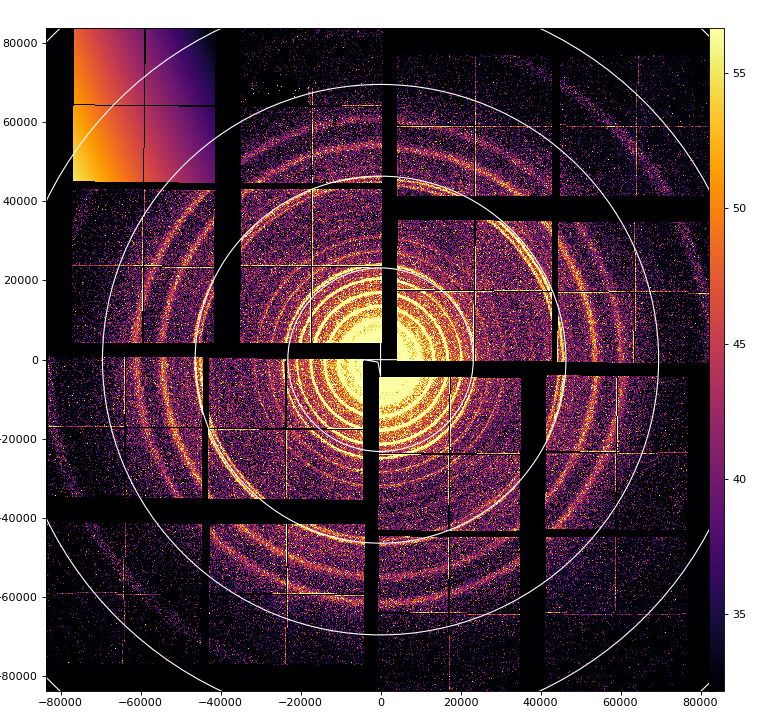
Summary:
- numeration of quads at rotation looks symmetric - so seems right
- one orientation of the detector gives correct image and it shows smallest offsets between panels in quads
mfxc00118 run44 silver-behenate


mfxc00318 run 10,13 lysozyme

References
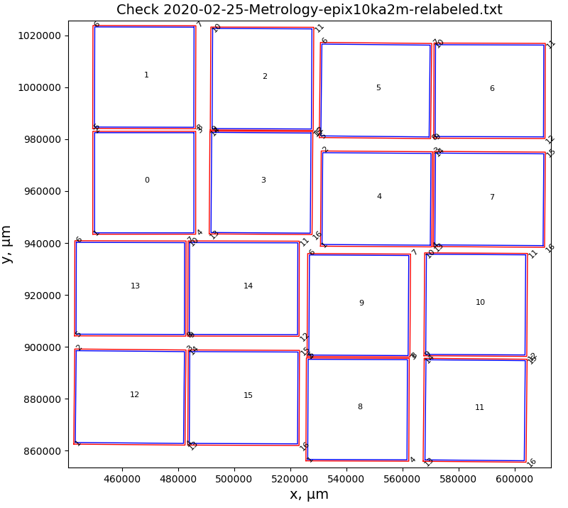
Optical metrology processed by script v0 (with quads) and v1 (without quads)
- red rectangles - for points measured in optical metrology
- blue rectangles - panels reconstructed from geometry file

DAQ panel indexes in optical metrology possible detector orientations
| Code Block | ||
|---|---|---|
| ||
        rot = 0  ^y
        Q0  1  3 |  4  5  Q1
            0  2 |  6  7
        ---------+----------> x
           15 14 | 10  8
        Q3 13 12 | 11  9  Q2

        rot = 1  ^y
        Q3 13 15 |  0  1  Q0
           12 14 |  2  3
        ---------+----------> x
           11 10 |  6  4
        Q2  9  8 |  7  5  Q1

        rot = 2  ^y
        Q2  9 11 | 12 13  Q3
            8 10 | 14 15
        ---------+----------> x
            7  6 |  2  0
        Q1  5  4 |  3  1  Q0

        rot = 3  ^y
        Q1  5  7 |  8  9  Q2
            4  6 | 10 11
        ---------+----------> x
            3  2 | 14 12
        Q0  1  0 | 15 13  Q3
|
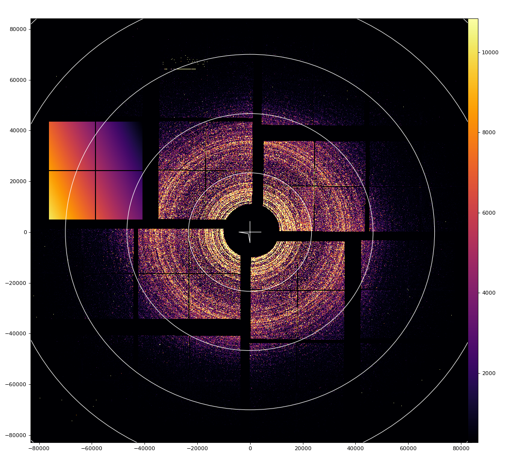
Images of panels in data for all detector orientations in metrology processing v1 without quads
- v1 of the metrology processing script represents simplest approach - each panel coordinates are taken as is to insert in the detector
- data from mfxc00118 run44 silver-behenate sample
- data panel 1 (numerated from 0 to 15) is replaced by intensity ascending array, darkest corner is (0,0) pixel.
Summary:
- numeration of quads at rotation looks symmetric - so seems right
- one orientation of the detector gives correct image and it shows smallest offsets between panels in quads
Detector orientation in the hutch
mfxc00118 runs 70-73 for Fe55 in the corner of quad 0-3
| Code Block | ||
|---|---|---|
| ||
   ^y          |
Q0 | Q1        |
---+----->x    |
Q3 | Q2 V g (gravity) |
Panel 0 data is replaced by the ascending intensity array, (0,0) pixel is in the darkest corner.
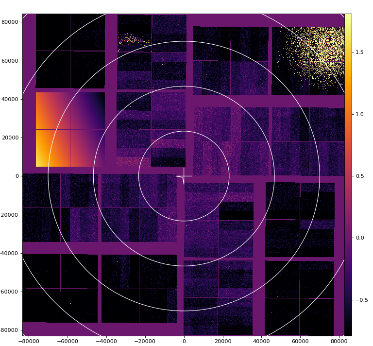


mfxc00118 run44 silver-behenate
panel 1 is marked

mfxc00318 run 10,13 lysozyme
psana direct and mirror image for crystfel
panel 0 is marked on full size image


Geometry files centered for mfxc00318 run13 lysozyme
- 2020-02-25-geometry-epix10ka2m.1-v1-mfxc00318-0013-z0.txt
- 2020-02-25-geometry-epix10ka2m.1-v1-mfxc00318-0013-z0-mirror.txt
- 2020-02-25-geometry-epix10ka2m.1-v1-mfxc00318-0013-z0-mirror-crystfel.txt
Geoptimizer or how geometry can be screwed-up
First, thanks to Olexandr and Marina for discovering how our geometry should be mapped to data array.
| Code Block | ||||
|---|---|---|---|---|
| ||||
Yefanov, Oleksandr <oleksandr.yefanov@cfel.de> Tue 8/18/2020 1:18 PM
To: Dubrovin, Mikhail; O'Grady, Paul Christopher
Cc: Hart, Philip Adam; Chun Hong Yoon <chuckyoon@stanford.edu>; Batyuk, Alex; Mariani, Valerio; McKelvey, Mark E
2 attachments (5 MB)Download allSave all to OneDrive - SLAC National Accelerator Laboratory
Hi Michail and others,
We’ve found the problem!!!!!
Hi Michail and others,
We’ve found the problem!!!!!
Sorry to say, but it’s from your side. :)
Solution at the end of the e-mail as a bonus for those who read the whole e-mail. :)
Actually I’ve written the e-mail while searching for the answer. But the text might be useful for those who work with geometries.
I believe that the optical metrology is right – I was wrong once, by thinking that CS-PAD metrology was not good and I don’t want to repeat my mistake. :)
But as with CS-PAD I’m afraid the problem is with attributing the optical metrology to the measured data. (here I’m right – see below :)
Unfortunately your arguments about influence of z-offset or out-of-plane tilts can be discarded using simple math.
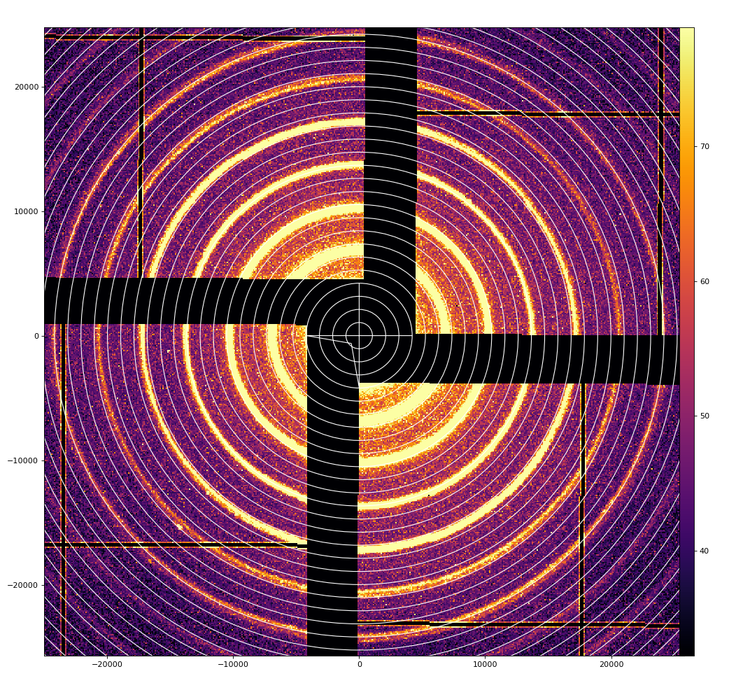
For example at the attached image (…current.png) the middle green ring has radius of 200px = 20mm and the detector is approx. at 120mm. So to have in-plane offset of 2 pixels you’d need to shift a panel by 2mm. That’s too much. Also, as you can see, at left-bottom panel the rings overlap at the top side, but have distance at the left side of the panel. So to correct it you’d need out-of-plane rotation. 2 pixels (at 200px distance) would correspond to 11.5 degrees. Not realistic. :( And in the attached example error is 4-5 pixels!!! I’m not even mentioning that in case of the tilts and z-offset the behavior is different at different parts of the panel. You can see the effect of these distortions from geoptimizer’s error map.
The interesting observation is that I really see z-offset for panels and it is quite big (up to 1mm for corner panel). Fortunately in my algorithm z-offset cannot be confused with x-y (different parameter is considered), but as I mentioned, due to the geometry of the detector z-offset is much more sensitive to noise/error (for example wrong peaks). Therefore to find reliable z-offset of different panels I need more data. I’ve made a very good geometry for AGIPD (with z-offset up to 1mm) using ONLY measured data (optical metrology doesn’t exist for AGIPD), so it is actually possible. I’ll try to optimize z later when I have access to more data.
Now SOLUTION !!!
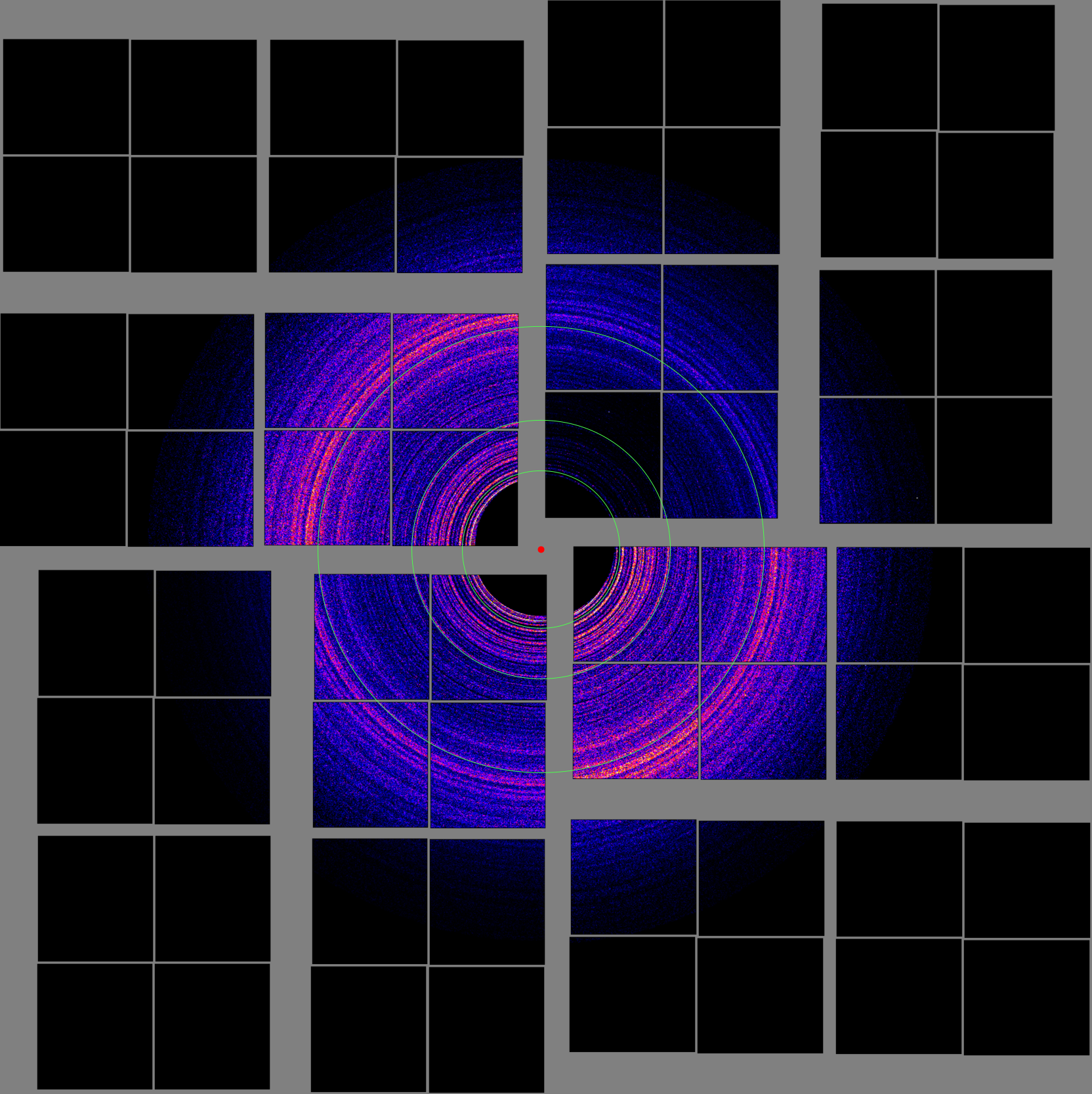
My student Marina tried to “rotate” the geometry – shifting the ss coordinate by 1408, 2816 and 4224 (1,2,3 quadrants). Apparently shift by 4224 gives correct geometry!!! Have a look at the attached shift4224.png. I’ve also indexed the data and checked with geoptimizer – it looks right (except z-offsets).
So please modify in this way your script that makes the geometry from metrology. Don’t forget to rotate the geometry to have visually correct detector – it doesn’t matter for SFX, but nice for users.
Please share the resulting geometry – I’d like to use it.
And I’ll try to add z-offsets to your resulting geometry when I have more data.
And Mikhail, I really want to thank you very much for good optical metrologies! It really saves users a lot of time!
Regards,
Oleksandr. |
However, before solution was found, geoptimizer returned geometry which is significantly different from optical metrology, as shown in movie comparing panels before (from opt metrology) and after optimization.

- It is clear that blind application of geoptimizer may cause >1 mm offset of panels in x-y ...
- It is suggested to use geoptimizer for panels with fixed center and panel orientation in (x,y) from optical metrology and apply optimization for z coordinate and off-plane tilts. Z coordinates were not measured correctly in optical metrology.
- Next optical metrology is expected to be with precise (~10um) Z measurement.
References
- EPIX10KA2M References
- Optical metrology of epix10ka2m.0 from 2018-11-18
- Optical metrology of epix10ka2m.0 from 2020-06-25
- EPIX10KA2M and EPIX10KAQUAD
- EPIX10KA panel flatness measurementEPIX10KA2M and EPIX10KAQUAD
Overview
Content Tools