...
 |  |  |
|---|---|---|
| Run 684 beam spot from 3rd MIMOSA plane | Run 684 RD53A (A97) hit map | |
 |  | |
 |  |
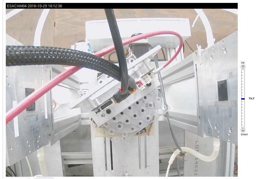
tilt photo for run 686,687
Plots from tilted Run 686:
 |  | |
|---|---|---|
 |  |
7:40 stop testing A97, replace with B53.
7:59 starting with the Tuned chip config file from LBNL for beamtest. B53 hase tens of very hot pixel. Need to mask the hot pixel.
~8:20, shut down beam to run quick digital/analog/thresold scan. The analoy scan pick out all the hot pixel and automaticly mask them out.
8:54, beam test with the new config file, looks like most of noisy pixel are quiet now.
| Run | Start | End | Event | Particle rate | Tilt | Comments |
|---|---|---|---|---|---|---|
| 714 | 8:54 | 9:02 | 2107 | 35 | 0 | noise pixel masked, stopped because of beam change |
9:03 beam change, so no beam for ESA. Beam is expected to be back after ~15mins
stop at 9:24.
Dec/13 Night shift
Zijun, SD
T578 HGTD period starts today but they are not ready to run until Saturday. Some additional time for ITk at the mean time.
Surrendered the HSIO2 Ethernet cable (Belden ch 8) to HGTD setup and the ESA-RESTRICTED network ports on the ESA switch 25-48 is completely jammed full. Took a long time to find Belden ch 24 is for power strip on an unused rack just outside the ESTB tunnel mouth. Displaced that cable at Ch 24 with Ch 11 cable connected to HSIO2 to bring that back int the network.
Night shift got Howard to produce a new setup to derive a 12.65 GV secondary beam for the 14.65 GeV primary beam. It looks like this set can work with the remaining night shifts of this period, but Day shifts with MEC starting Saturday is 10 GeV primary beam which needs a separate setup to run 8 GeV secondary. The tuning of the 12.65 secondary beam had a few surprises with momentum cuts moving spot location etc. We settled with a round beam spot covering ~1/3 of the MIMOSA at ~70 particles/pulse. The beam spot is shift by a few mm in -X and -Y which needed to move whole Caladium to recenter.
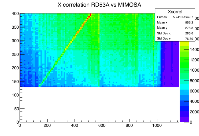
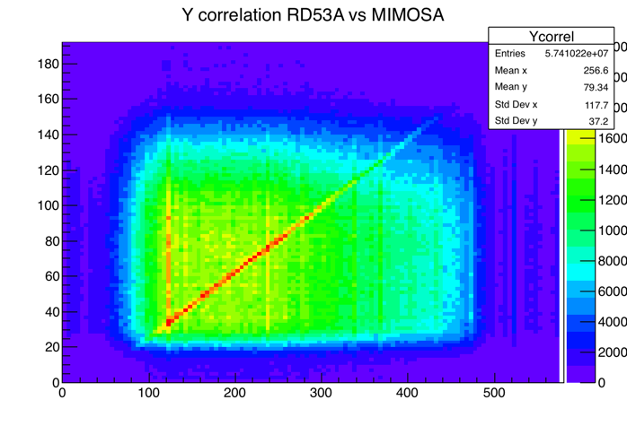
Whole shift of test runs debugging the loss of event ID match between Caladium and RD53A readout. Some runs got good MIMOSA vs RD53A X,Y correlation at start at least and other runs were not aligned. There were some odd extra event looking like real distinctive RD53A beam hit data at DUT readout but never found a matching MIMOSA event data. TLU ch-1 RJ45 port is somewhat suspicious and sometimes could not communicate with FEB. Moved FEB link to TLU ch 2. More stable communication to FEB, but the issue of extra event on RD53A side remains.
Dec/14 Night shift
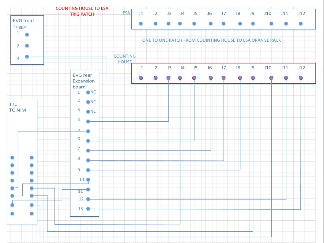
Day shift: UCSC T788 setup continues during MD. One main issue to resolve is the dead Trg-10 for Caladium. T578 needs both Trg-10 (NIM for Caladium) and Trg-11 (TTL for HGTD). Didn't manage with connect with Doug to debug the dead Trg-10, but he passed on a schematic for the ESTB trigged patch scheme:
 |  | |
|---|---|---|
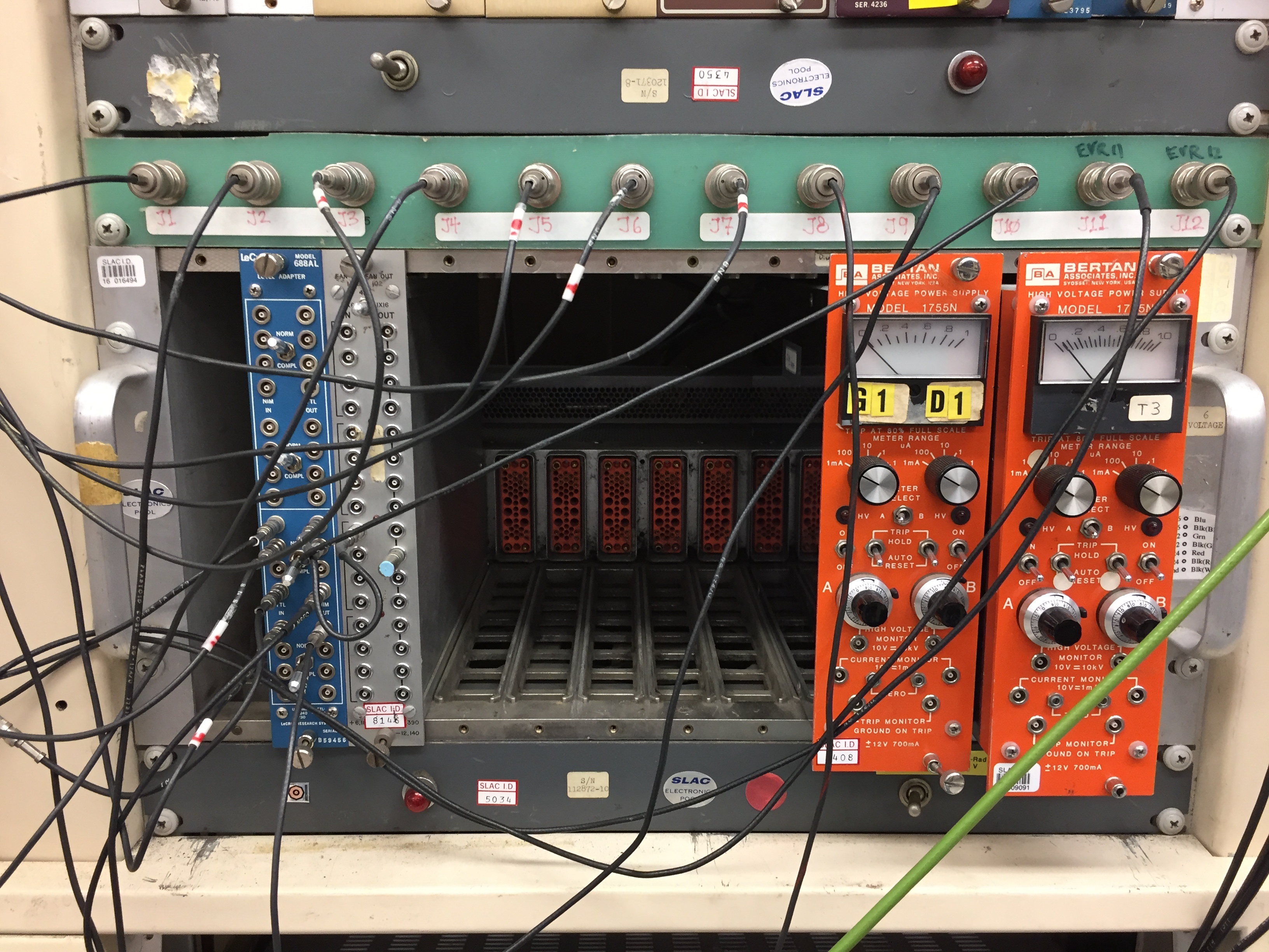
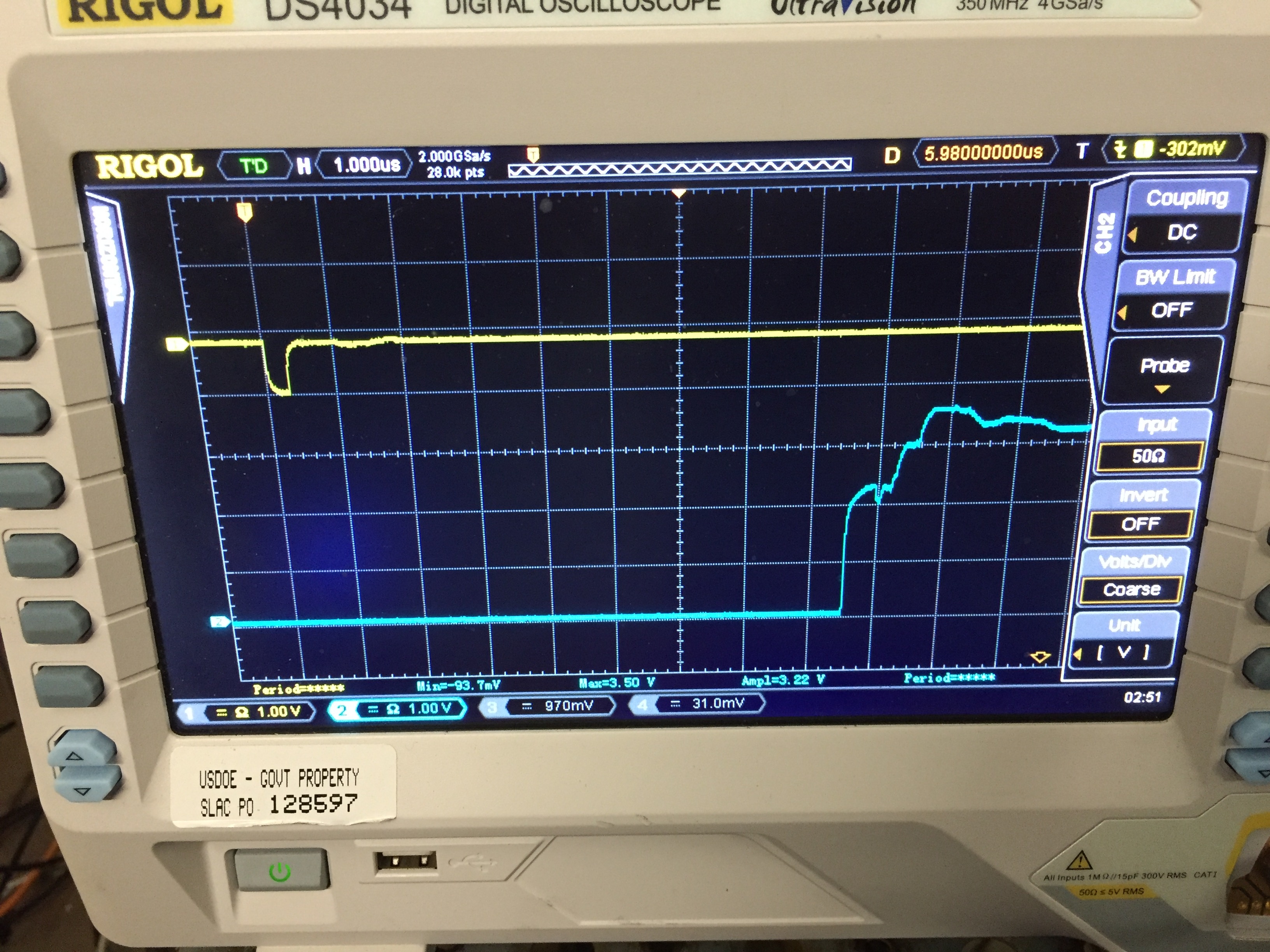
| Counting house patch panel. Note the very taught LEMO cable leading to J10. | Yellow=Trg-10 (NIM); Cyan=Trg-11 (TTL) at Caladium rack. The 8.5us delay between them seems to commensurate with the delay panel settings: (-102010) - (-110488) = 8478 |
The issue with Trg-10 is not obvious: EVG rear expansion board ch 11 (LVTTL?) is one of the inputs (the other input is EVG Front trigger 2) to the Lecroy level adaptor in compl mode tuning that into a 1.2V and 300ns width NIM. The only part looking suspicious is the LEMO cable taking the NIM output to J10 looks very tight. Replaced that part with a slightly longer cable. This did effectively bring the Trg10 NIM signal back to Caladium rack but signal shape weak. Decided to connect J10 directly to EVG rear 11 to send TTL signal over long path to tunenel and used TTL->NIM at caladium rack for a much more solid NIM signal to TLU.
Night shift: ZiJun,SD
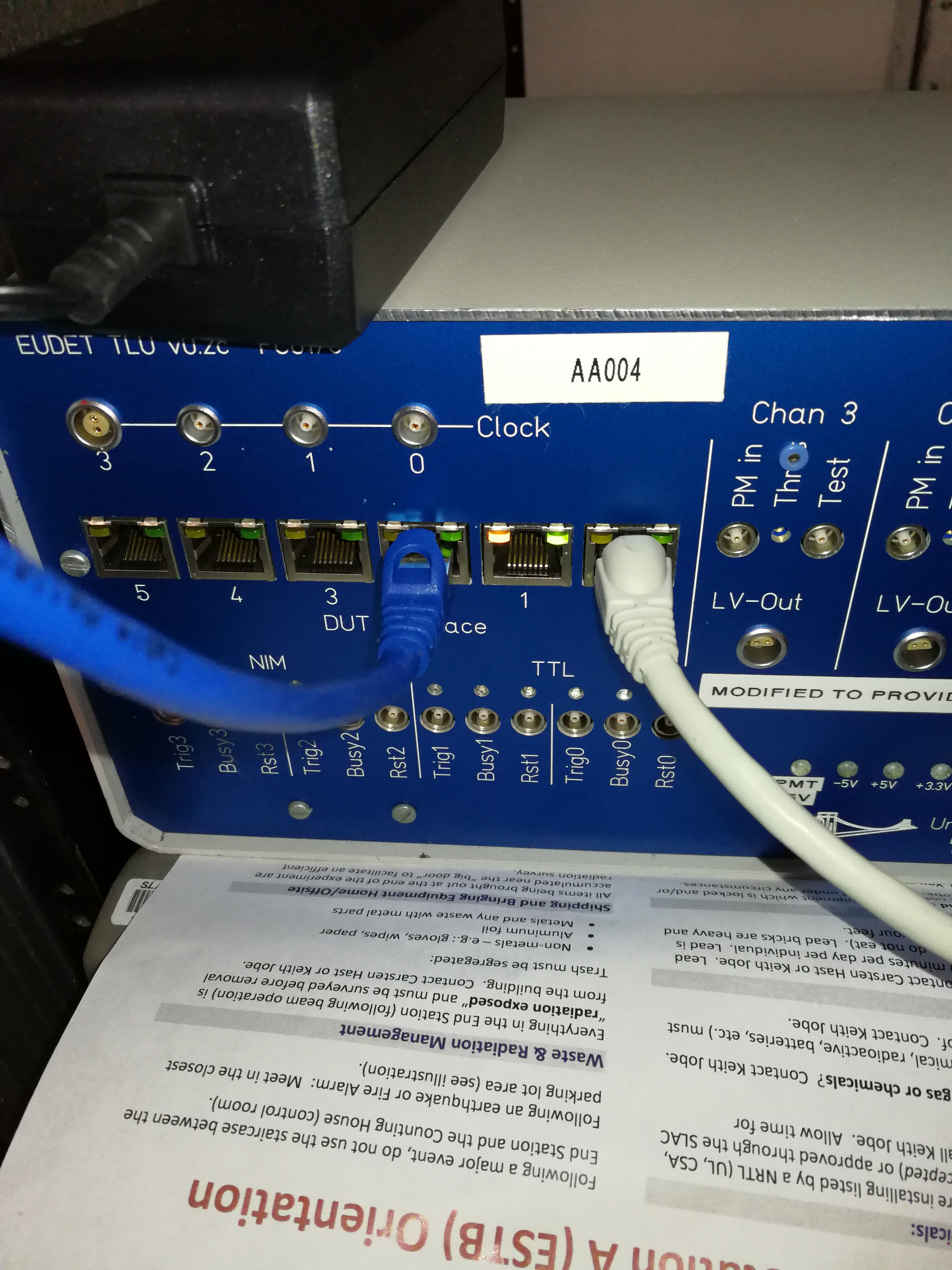
Finally, realized that TLU RJ45 ch1 defect is one of the reasons for events synchronization failure between MIMOSA and RD53a.
1) FEB can not get trig signal from TLU ch1;
2) MIMOSA can receive trigger signal from TLU ch1, but the TLU words from TLU ch1 are wrong. Left plot is the TLU words distribution from ch1, while right plot is the TLU words from ch0.


Now, connect TLU ch0 to MIMOSA, and ch2 to FEB.
 | |
|---|---|
| Dec/11 11:54pm. Applies to Run 653-684. Beam L->R. | Tilt just before Run 686-688. Beam R->L. |
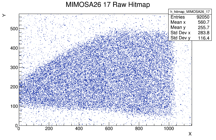
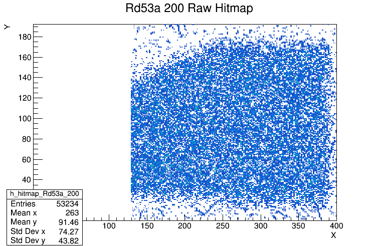
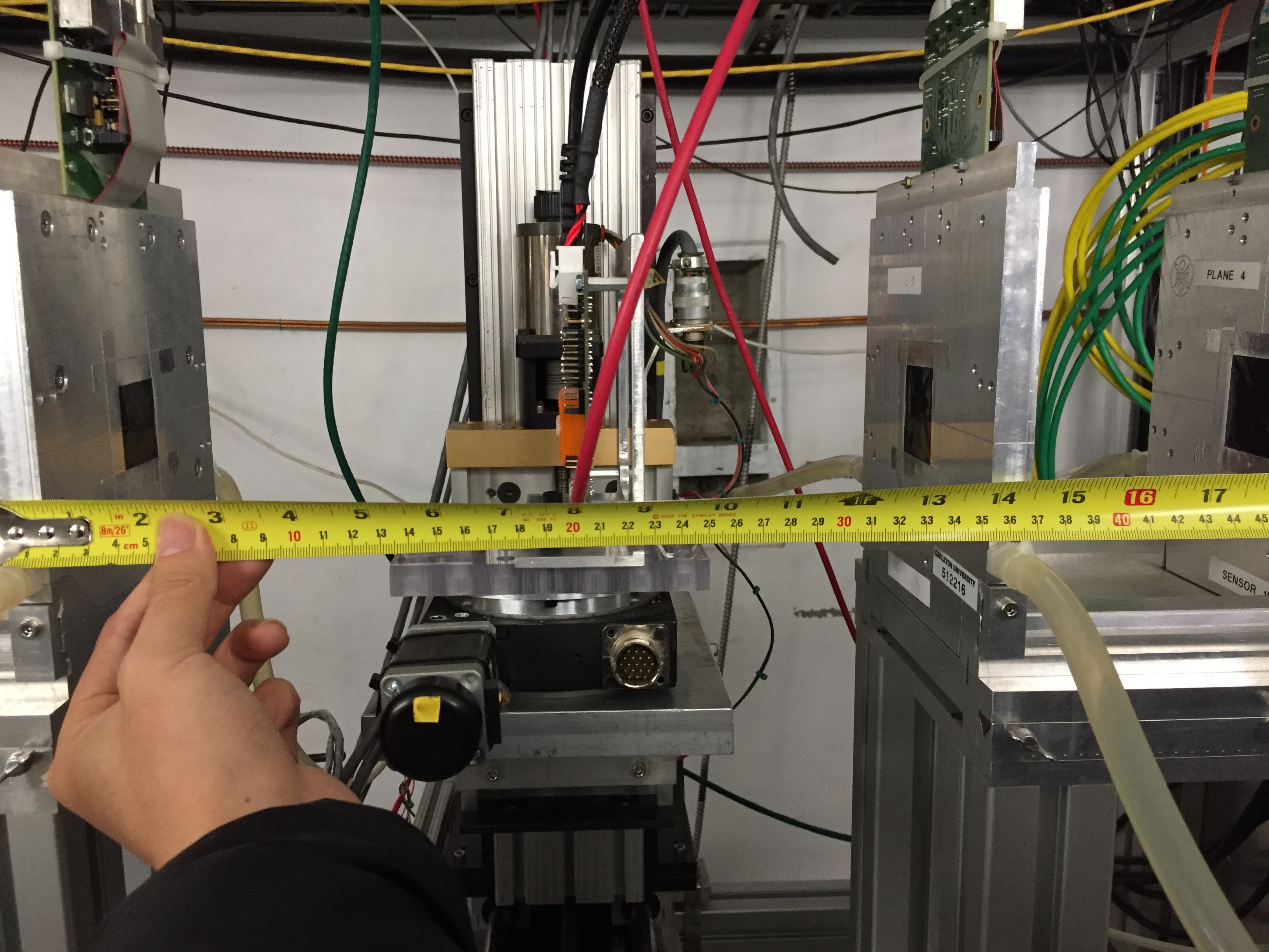
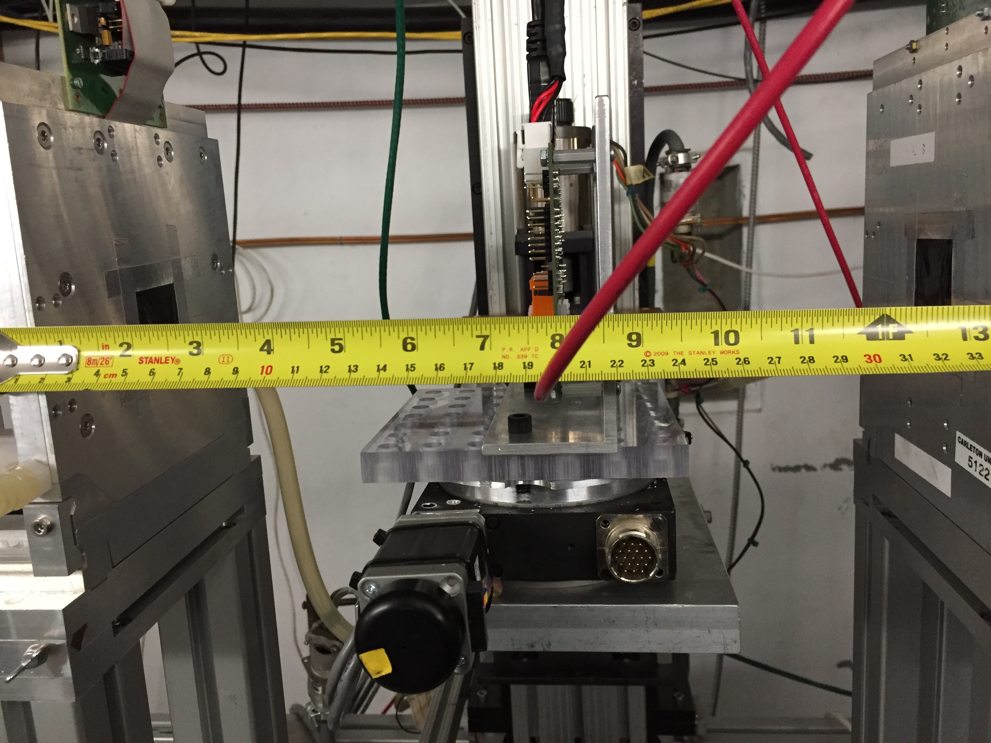
MIMOSA and DUT positions: Caladium was measured in Jan/2016 session as documented in the Jan/2016 commissioning session Twiki which should be still correct for the plane separate of 152mm between the 3 front planes, and between the 3 back planes. However, the DUT gap looks like was increased to 357mm from the original 307mm, probably when we tried to insert the dry ice foam box for irradiated DUTs. We typically measure the DUT gap with tape header clipped to the front face of the 3rd EUDET plane as shown above. In this tape coordinate, the 3rd MIMOSA plane is at z=2.65mm behind the EUDET support metal front face (see EUDET hardware wiki). RD53A DUT (right edge of orange box) looks like to be at z~204mm which would imply the RD53A plane is at ~201.5mm behind the 3rd EUDET plane. When tilting with remote DUT rotation, the XZ transformation is unfortunate dependent on the mounting of the DUT and the rotation is not centered around DUT device so that it changes the mean z coordinate and also needs a DUT x shift to bring back to the beamline.
Plots from tilted Run 686:
| | |
|---|---|---|
| |
7:40 stop testing A97, replace with B53.
7:59 starting with the Tuned chip config file from LBNL for beamtest. B53 hase tens of very hot pixel. Need to mask the hot pixel.
~8:20, shut down beam to run quick digital/analog/thresold scan. The analoy scan pick out all the hot pixel and automaticly mask them out.
8:54, beam test with the new config file, looks like most of noisy pixel are quiet now.
| Run | Start | End | Event | Particle rate | Tilt | Comments |
|---|---|---|---|---|---|---|
| 714 | 8:54 | 9:02 | 2107 | 35 | 0 | noise pixel masked, stopped because of beam change |
9:03 beam change, so no beam for ESA. Beam is expected to be back after ~15mins
stop at 9:24.
Dec/13 Night shift
Zijun, SD
T578 HGTD period starts today but they are not ready to run until Saturday. Some additional time for ITk at the mean time.
Surrendered the HSIO2 Ethernet cable (Belden ch 8) to HGTD setup and the ESA-RESTRICTED network ports on the ESA switch 25-48 is completely jammed full. Took a long time to find Belden ch 24 is for power strip on an unused rack just outside the ESTB tunnel mouth. Displaced that cable at Ch 24 with Ch 11 cable connected to HSIO2 to bring that back int the network.
Night shift got Howard to produce a new setup to derive a 12.65 GV secondary beam for the 14.65 GeV primary beam. It looks like this set can work with the remaining night shifts of this period, but Day shifts with MEC starting Saturday is 10 GeV primary beam which needs a separate setup to run 8 GeV secondary. The tuning of the 12.65 secondary beam had a few surprises with momentum cuts moving spot location etc. We settled with a round beam spot covering ~1/3 of the MIMOSA at ~70 particles/pulse. The beam spot is shift by a few mm in -X and -Y which needed to move whole Caladium to recenter.
Whole shift of test runs debugging the loss of event ID match between Caladium and RD53A readout. Some runs got good MIMOSA vs RD53A X,Y correlation at start at least and other runs were not aligned. There were some odd extra event looking like real distinctive RD53A beam hit data at DUT readout but never found a matching MIMOSA event data. TLU ch-1 RJ45 port is somewhat suspicious and sometimes could not communicate with FEB. Moved FEB link to TLU ch 2. More stable communication to FEB, but the issue of extra event on RD53A side remains.
Dec/14 Night shift
Day shift: UCSC T788 setup continues during MD. One main issue to resolve is the dead Trg-10 for Caladium. T578 needs both Trg-10 (NIM for Caladium) and Trg-11 (TTL for HGTD). Didn't manage with connect with Doug to debug the dead Trg-10, but he passed on a schematic for the ESTB trigged patch scheme:
| | |
|---|---|---|
| Counting house patch panel. Note the very taught LEMO cable leading to J10. | Yellow=Trg-10 (NIM); Cyan=Trg-11 (TTL) at Caladium rack. The 8.5us delay between them seems to commensurate with the delay panel settings: (-102010) - (-110488) = 8478 |
The issue with Trg-10 is not obvious: EVG rear expansion board ch 11 (LVTTL?) is one of the inputs (the other input is EVG Front trigger 2) to the Lecroy level adaptor in compl mode tuning that into a 1.2V and 300ns width NIM. The only part looking suspicious is the LEMO cable taking the NIM output to J10 looks very tight. Replaced that part with a slightly longer cable. This did effectively bring the Trg10 NIM signal back to Caladium rack but signal shape weak. Decided to connect J10 directly to EVG rear 11 to send TTL signal over long path to tunenel and used TTL->NIM at caladium rack for a much more solid NIM signal to TLU.
Night shift: ZiJun,SD
Finally, realized that TLU RJ45 ch1 defect is one of the reasons for events synchronization failure between MIMOSA and RD53a.
1) FEB can not get trig signal from TLU ch1;
2) MIMOSA can receive trigger signal from TLU ch1, but the TLU words from TLU ch1 are wrong. Left plot is the TLU words distribution from ch1, while right plot is the TLU words from ch0.
Now, connect TLU ch0 to MIMOSA, and ch2 to FEB.
5:26 am New version of YARRproducer stabilized the synchronization between MIMOSA and RD53a readout. Previous version used local event counters with no direct check of event ID to confirm synchronisity. It was seen that 5:26 am New version of YARRproducer stabilized the synchronization between MIMOSA and RD53a readout. Previous version used local event counters with no direct check of event ID to confirm synchronisity. It was seen that block of e.g. 1000 events are offset by a few events between MIMOSA and RD53a, and then this offset would slip every ~1000 events so that sometimes by chance the synchronization is achieved by luck and then slips off again after a while. New version defies the RD53a event number using the TLU distributed event number (offset by 1) to automatically achieve synchronization.
...
| Run | Start | End | Event | Particle rate | Tilt | Comments |
|---|---|---|---|---|---|---|
| 777 | 5:06 | 5:39 | 10015 | 54 | 0 | First run with new event counter follow TLU. DUT=B53. |
| 779 | 5:40 | 5:42 | ~1300 | Turned on Synchronous FE briefly | ||
| 781 | 5:52 | Turned on Synchronous FE briefly | ||||
| 781 | 5:52 | 54 | 55 | Event ID offset=1 | ||
| 782 | 6:03 | 6:34 | 10003 | 54 | 55 | Correlation good again |
Run 781-782 tilt configuration
| 54 | 55 | Event ID offset=1 | ||||
| 782 | 6:03 | 6:34 | 10003 | 54 | 55 | Correlation good again |
|  |
|---|---|
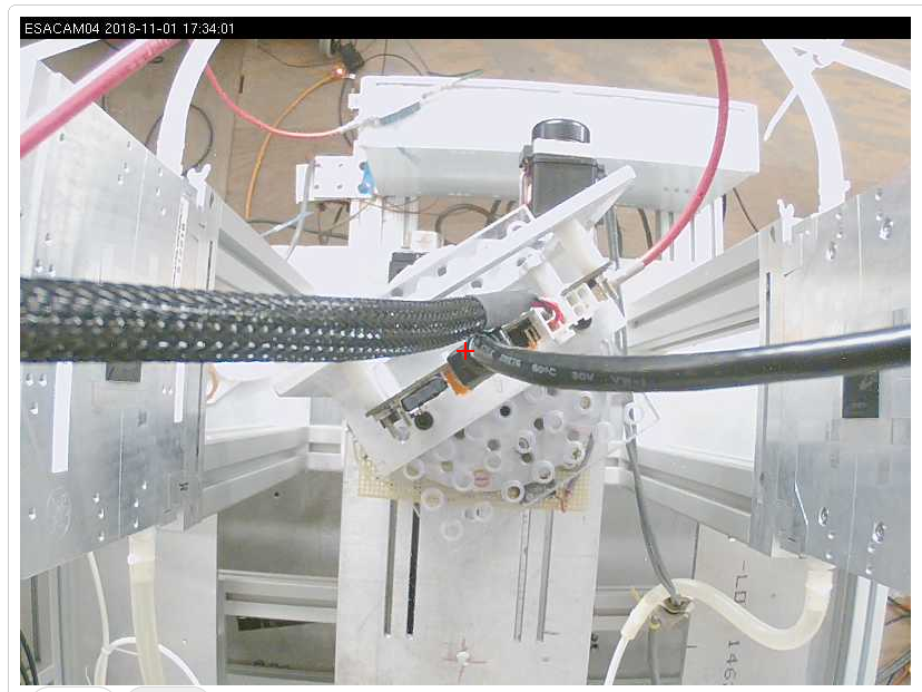
| Run 781-782 B53 Tilt position from CAM. Beam R->L. | Dec/15 6:41am remiss of Run 781-782 config. Beam L->R. |
|  |
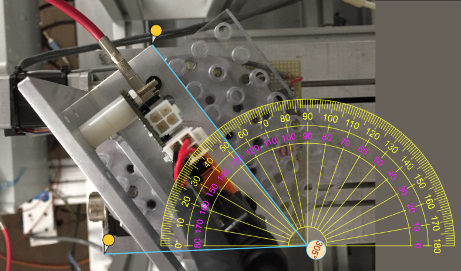
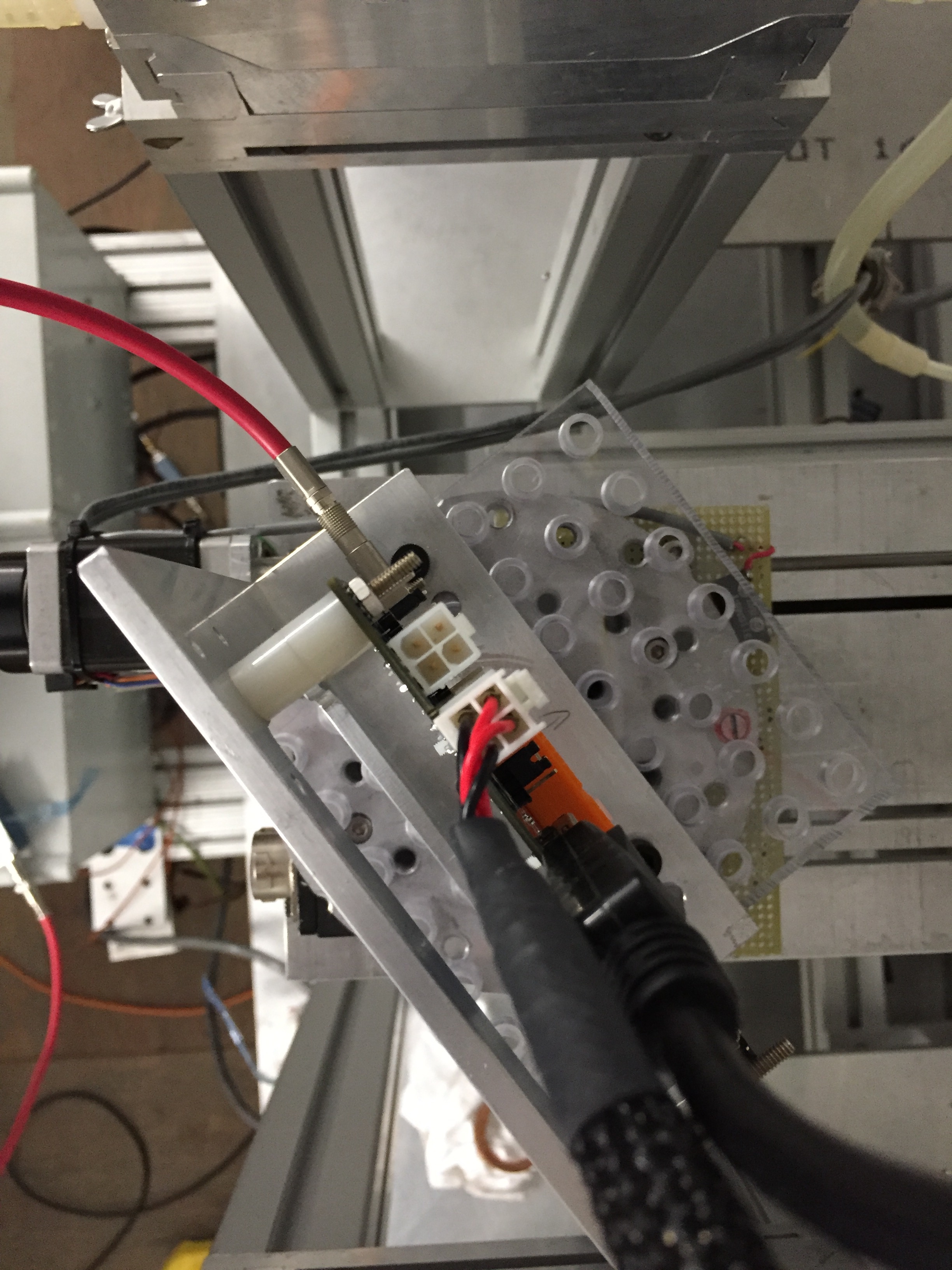
| For Run 781-782 with B53. Beam Up->Down at 87deg. | Dec/15 6:45am. A97 mounted, before Run 785. |
6:35 Requested access to change DUT to A97 (25x100um pixel). and mounted at 0 degrees. Also checked the Trg-10 NIM signal - now back. Remeasured the B53 tilt position before switching to A97. While the DUT plane angle to beam was fairly precisely measured at 55deg. The Longitudinal position is not easy to determine from photos. A very rough estimate was the DUT center was ~213mm after 3rd EUDET plane. New 0 deg DUT A97 with tape clip z~198.5mm implies ~196mm after 3rd EUDET plane. 7:00 Requested access to change DUT to A97 (25x100um oixel). and mounted at 0 degrees. Also checked the Trg-10 NIM signal - now back.
8:10 Lowered particle rate to ~4 clus/mimosa and 0.6/pulse on RD53a 2/3 FE area. Hit spread pretty uniform.
...