Design and Layout of LSS
PLC Installation
Module Installation
- Connect 28-pin cable (circled in blue) from each input/output module to its corresponding input/output terminal block.
- Connect cable from 15-pin port on PLC module (circled in orange) to 9-pin port on RS232 converter (pictured below).

- Wire positive and negative terminals (circled in green) to those of the Quint Power Supply Unit (pictured below).
Installing and Connecting Breakout Modules
Power
PLC Programming
Installing DirectSoft
- Download the software installer from https://support.automationdirect.com/products/directsoft.html.
- Install the latest version of DirectSoft.
- License Key: QKGD-6L68-Y019-J117
Connecting to the PLC
- Plug HDMI cable into Port 1 (circled) of PLC module.
- USB adapter will be needed to connect to computer.
- PLC must be in terminal mode ("TERM") to transfer changes.
- In the DirectSoft program, navigate to the toolbar and click the dropdown menu labelled “PLC”.
- Select "Connect...".
- If the PLC has never been connected to the computer before, create link.
- In the “Select Link…” pop-up window, click “Add…”.
- Select the communications port that the PLC is connected to.
- This may be found in the Device Manager of your computer’s Control Panel
- Select the PLC’s product family.
- Example: DirectLogic205 will be from the DL 0/1/2/4/350 Family
- Select the protocol to use in the communications link.
- SLAC LSS uses K Sequence
- Address: 1
- In the “Select Link…” pop-up window, click on the PLC you are using and press “Select”.
Port Settings
- Navigation
- Navigate to the toolbar and click the dropdown menu labelled "PLC".
- Roll-over "Setup" and select "Setup Sec. Comm Port..." from the dropdown menu.
- Settings
- Port 2
- Non-Seq(ASCII)
- Base Timeout
- Data bits: 8
- Baud rate: 9600
- Stop bits: 1
- Parity: None
- Memory address: V7000
- Write the new settings to the PLC by clicking the icon:

Common Program Rungs
- Standard Order of Code
- Reset all variables
- Set necessary variables
- Shutter section
- Interlocks and latches
- Mode changes inhibited
- Logic section
- Bypasses
- Mode selection
- In order from the mode with the least privileges to the mode with most privileges
- Lights
- Signs
- End
- Alternating On/Off
- For blinking lights, special buzzer patterns, etc.
- Example code (for use with EO buttons):

- Signs
- PRINT Box
- Port: K2
- Script example: “_00_00_00_00_00_01Z00_02A0_1B b_1A9_1C1LASER IMMINENT _04”
- Start of header
- “_00_00_00_00_00
- Define sign address
- Broadcast to all signs: _01Z00
- Message for signs with specific address: _01Z01, _01Z02, _01Z03, etc.
- Start of text string
- _02A0
- Text dynamics
- Scrolling: _1B a
- Static: _1B b
- Text height
- _1A#
- may be 1-9, with 9 being full height
- Text color
- Red: _1C1
- Green: _1C2
- Yellow: _1C3
- Write message text
- Example: LASER IMMINENT
- End string
- _04"
- Start of header
- Only send print command to sign once
- Reset print command immediately after setting
- PRINT Box
Touch Panel Installation/Programming
Installing the Touch Panel
- Mounting and Connecting to Power
- The C-more touch panel order with come with the touch screen, mounting clips, and a terminal block.
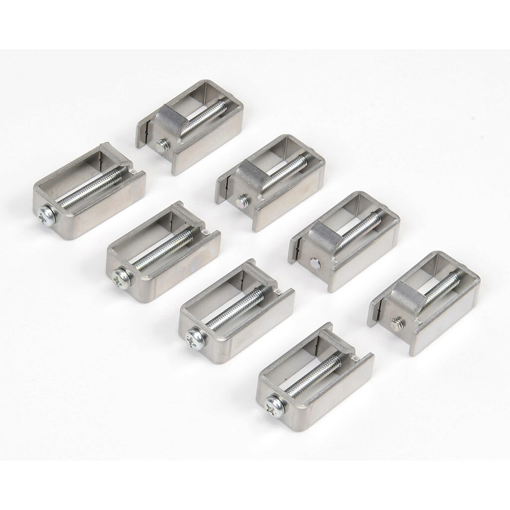
- Use the mounting clips (pictured below) to secure the panel, from the inside, to LSS box door.
- Secure terminal block to back of panel.
- Connect one black wire (GND) from the ground terminal to grounded contact on rack.
- Ground terminal is second from the bottom and will be labelled with the ground symbol.
- Connect one blue wire (power) from the negative terminal to 24V contact on rack.
- Negative terminal is third from the bottom and will be labelled with a minus sign.
- Connecting to the PLC
- Connect HDMI cable from 15-pin port on back of panel to Data Communications Module port (pictured below).
- Connect HDMI cable from 15-pin port on back of panel to Data Communications Module port (pictured below).
- Connecting to Computer
- To upload new code, connect USB Cable from port on back of panel to port on computer.
Installing C-more
- Download the C-more software
- https://www.automationdirect.com/support/software-downloads?itemcode=C-more%20EA9%20Series
- NOTE: some existing LSS still use EA7
- License Key: 7UGA-R9M6-3FKY-6TQV
- https://www.automationdirect.com/support/software-downloads?itemcode=C-more%20EA9%20Series
- Connect to the PLC
Programming Common Objects
...
- Choose objects from Object Library on right-hand side of screen
- Or use "Object" drop-down menu at top of screen
- Example LSS Touchscreen.pdf
- Example LSS Touchscreen.eap
...
- Used to link an object with a variable in the DirectSoft code
- Add tag names
- Navigate to the toolbar and select the drop-down menu labelled "Database"
- Click "Tag Name Database..."
- Click the "Add" icon at the top of the pop-up window
- Device Name = DEV001
- In the "Tag Name" entry box, type the desired nickname
- Tag Data Type = Discrete
- Select Memory Type from drop-down menu
- C variables are internal
- X variables are physical inputs
- Y variables are physical outputs
- V variables are used for loading bits into
- Enter address
- Make sure this matches the variable in DirectSoft
- Click "Add"
...
- Pushbuttons are used to toggle variables between on and off.
- Usually linked to an X variable.
- Use different background colors to differentiate between a button's on and off states.
...
- Indicator lights are used to display variable status.
- Usually linked to a Y variable.
...
Each bit corresponds to a K value:
...
- Used for menu to toggle between pages
- Insert at bottom of new screen
Common Components Installation
General
- Use 22-gauge copper wire unless states otherwise.
- Color-code wires
- Blue = power
- Yellow = signal
- Black = ground
*subject to variability between hutches/components
LED Signs
EO Buttons


- P/N: XW1E-LV
- Connect 24V wire to terminal 4 and input signal wire to terminal 3.
- Connect 24V wire to X1 and output signal wire to X2.
Bypass Modules
Door Interlocks
Power Supply Enables
Enclosure Interlocks
Stack Light

- 5-pin Cable
- Blue = 24 V
- Black = Input 1 (green)
- Brown = Input 2 (red)
- Datasheet