Thanks to Matt Weaver, Kukhee Kim, Mike Zelazny, Justin Chen and Ernest Williams. -Author: Carolina Bianchini Mattison
What does SC Timing Provides:---------------------------------------------------------------------------------------------------------------------------------------------------------------------------------
SC Timing Patterns from LCLS-II Project for Commissioning:
- AC Rates (using Timeslot 3 and 6): 0Hz, 1Hz, 10Hz, 30Hz, 60Hz, 90Hz, 110Hz, 119Hz, 120Hz
- Fixed Rates: 0Hz, 1Hz ,10Hz, 50Hz, 100Hz, 120Hz, 200Hz, 500Hz, 1KHz, 1.4KHz, 5KHZ, 10KHz, 23KHz, 33KHz(special req. not in Tab 4 from PRD), 46KHz, 93KHz (special req. not in Tab 4 from PRD), 464KHz, 929KHz
The patterns 1) can be interleaved between multiple destinations (SC_DIAG0, SC_BSYD, SC_HXR, SC_SXR, SC_DASEL) up to max 120Hz total.
The patterns 2) can also be interleaved between multiple destinations (SC_DIAG0, SC_BSYD, SC_HXR, SC_SXR, SC_DASEL) up to max 929KHz.
And Special Triggers:
The Timing System provides the following Controls Sequence bits to satisfy other requirements. Such as:
- BPM Calibration bit, this bit is asserted to allow BPM calibration in between beam pulses when rate is less than 100Hz. This calibration bit can be found by selecting:
Rate Mode = Expt, Expt Seq Number = 1, Expt Seq Bit = 0, Destination Mode = Disable
- Keep Alive Trigger, beam request for SC_BSYD, this bit always scheduled as part of all patterns to currently trigger as following:
- For Rates higher than 1KHz
SC_BSYD will have 100Hz
- For Rates lower or equal than 1KHz
SC_BSYD 10Hz
- For Rates lower or equal to 10Hz
SC_BSYD 1Hz
(This trigger was extensively discussed, and the above trigger logic was agreed upon and replaces previously requirement to be always set to 10KHz).
This trigger is set on Engine 15 to always maintain a high priority on beam requests over other engines but schedules the beam request for destination 2 SC_BSYD. The setup to trigger on this bit is to select:
Rate Mode = Same as Beam Fixed/AC, Rate = Max allowed {120Hz or 1MHhz} Destination Mode= include, Destn = 2
- Kicker Magnet standby triggers for beam request above 10KHz to the SC_BSYD, will consist in two bits one for HXR and one for SXR to match the undulator requested rate. This is needed to maintain the kicker trigger thermal stability. This is not a requirement for SC_DIAG0.
- Data Acquisition triggers to match beam pulse location respect the destinations: SC_HXR, SC_SXR for 1H, TH and HH. (TBD SC_BSYD)
User Guide Start
...
1) Access the timing trigger displays
 Image Removed
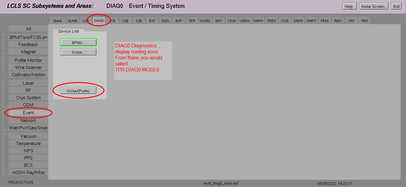 Image Added
$TOOLS/pydm/display/evnt/tprDiag.ui & $TOOLS/pydm/display/evnt/tprDiagExp.ui
*Add Example to how to open related display tprTrigger
*Autogen display from DB
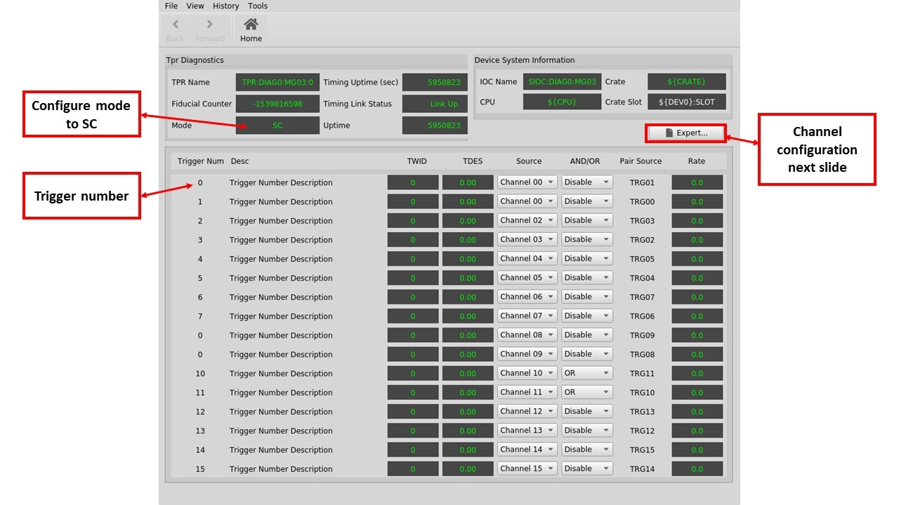 Image Added
*Fixing undefined macros Image Removed
2)General TPR Setup:
2a) Make sure the MODE PV is set to SC, Link is up and set the Message Delay
...
Example = 112597 nsec BPMS Message Dealy set in Diag0
Set through caput!
2b)Setup TPR Trigger
The Triggers are linked to the firmware by the Firmware Engineer, talk to the Firmware Engineer to find out what is associated with each Trigger and then set meaningful names to each trigger "Desc".
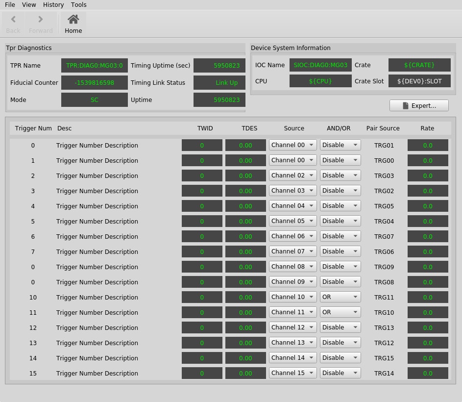 Image Added
*Change the TWID and TDES to enterable fields → Verify that SYS0 and SYS2 does update with Mode switching
*Allow to view NC and SC displays
$TOOLS/pydm/display/evnt/tprDiag.ui
This will help you understand how to setup the Channels used by your Triggers.
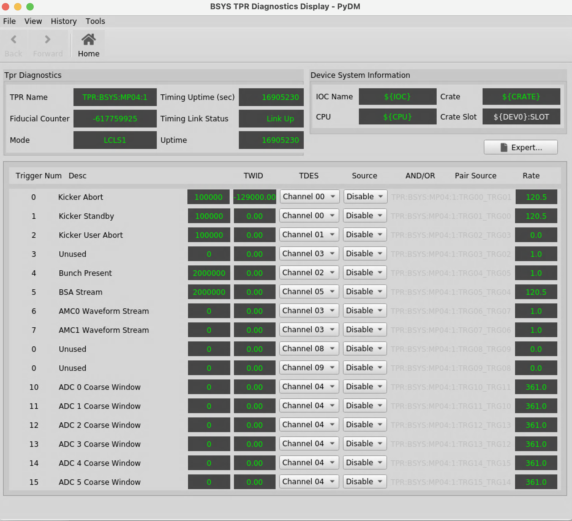 Image AddedPlease Note: This is an old TprTrigger module version but it is a Great example of naming your triggers!
$TOOLS/pydm/display/evnt/tprDiagExp.ui
Setup your Channel to be used as a Timing Pattern Filter, the Channel is the tool to use to filter the frames you want your system to trigger on.
3)Setup the Channels
The Channel This is a similar concept to an Event Code but it is configured at the Client (TPR) level instead of being globally defined in the TPG.
The Triggers are linked to the firmware by the Firmware Engineer, talk to the Firmware Engineer to find out what is associated with each Trigger and then set meaningful names to each trigger "Desc".
 Image Removed
The Channel is the trigger logic that allows you to trigger your system.
...
Channel 1: N Triggers This means you can configure a Channel and re-use it for multiple triggers, just like an event code but at the Client level.3)Setup the Channels
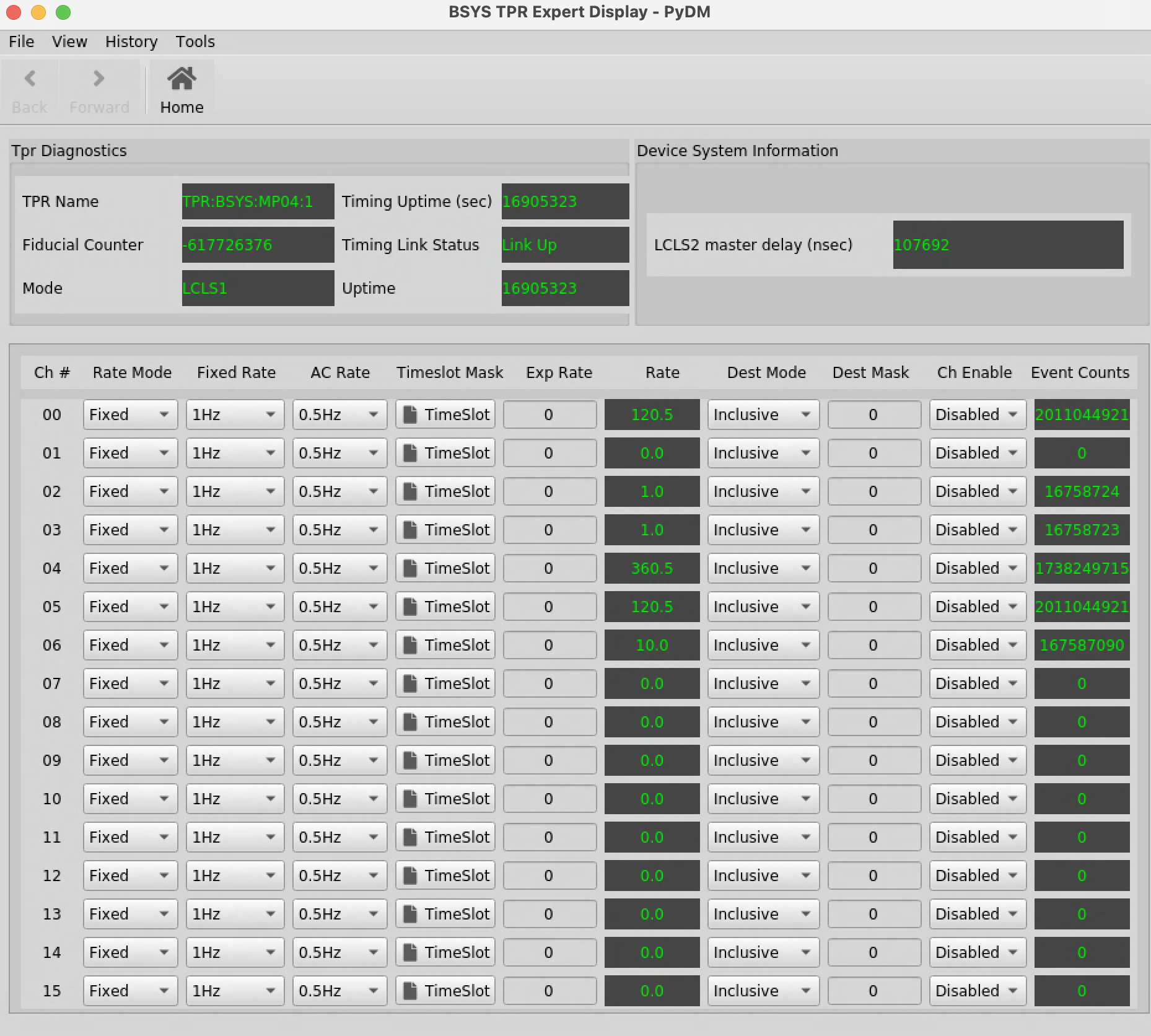 Image Added
The Channel has different sections that needs to be setup:
Q1) Do you need to trigger when a Destination is included?
LASER0X1
DIAG00X2
DUMPBSY0X4
DUMPHXR0X8
DUMPSXR0X10
LESA0X20
Q2) Do you need to trigger at a Lower Frequency?
if YES, AC or Fixed?
AC Rates out of the SC Laser will be scheduled on TS3 and TS6, keep this in mind!
Q3) Do you have a special trigger, like a Calibration, Kicker or BSA BUFF?
The SECTIONS of Channel setup are organized by column and repeated by row (x15 configurable channels)
Rate Mode can be Fixed, AC or Seq
Fixed Rates are 1Hz, 10Hz, 100Hz, 1KHz, 10KHz, 71.5KHz and 1MHz (929KHz) - If different, you are loading the wrong db!
AC Rates are 0.5Hz, 1Hz, 5Hz, 10Hz, 30Hz, 60Hz → To achieve 120Hz INCLUDE TIMESLOT MASK TS3 and 6!
*0.5Hz Please review DB → Should that be there?
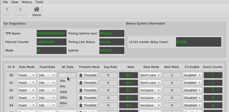 Image Added
Exp Rate → THIS SECTION NEEDS EDITS! Apologies...
Dest Mode= Inclusive, Exclusive or Don't care
Dest Mask = Enter Destination bit
Use Cases:
...
3a) Trigger based on a Destination receiving Beam
Rate Mode = Fixed
1MHz + Include Dest
Fixed Rate = 1MHz
Destination Mode = Include
Destination Mask = Dest Bit
Ch Enabled → Only when you are done configuring, to avoid high undesired triggers on your device!
This will trigger your device in either Fixed rate or AC Rate beam, anytime there is beam.
3b) Trigger based on Destination and Particular Rate (Device Rate Limited)
Fixed Rate
AC Rate
3c) Trigger based on a particular rate but no destination requirement
AC and/or Fixed Rate at a Lower rate than beam rate with Destination Requirement
Fixed Rate Case:
Rate Mode = Fixed
Fixed Rate = 10Hz
Destination Mode = Include
Destination Mask = Dest Bit
Ch Enabled → Only when you are done configuring, to avoid high undesired triggers on your device!
AC Rate Case:
Rate Mode = AC
AC Rate = 10Hz
Destination Mode = Include
Destination Mask = Dest Bit
Ch Enabled → Only when you are done configuring, to avoid high undesired triggers on your device!Dest Mode = Don't Care
3c)Trigger based on AC and/or Fixed Rate at a Lower a Lower rate than beam rate withOUT Destination Requirement
Fixed Rate Case:
Rate Mode = Fixed
Fixed Rate = 10Hz
Destination Mode = Don't care
Ch Enabled → Only when you are done configuring, to avoid high undesired triggers on your device!
AC Rate Case:
Rate Mode = AC
AC Rate = 10Hz
Destination Mode = Don't care
Ch Enabled → Only when you are done configuring, to avoid high undesired triggers on your device!
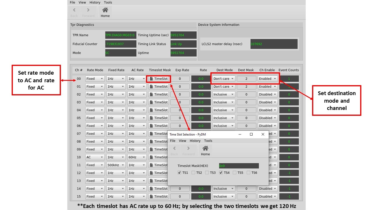 Image Added
 Image Removed
3d)
Trigger on special bits like the Calibration Bit for BPMS → Control Sequence Setup
...
Seq = # and bit = # & EXCLUDE dest = # this provides the out of time trigger.
Image Added
3e)Trigger on a SYS BSA Buffer at 1Hz, 10Hz, 100Hz → Control Sequence SetupA) For a specific area