Page History
Based on e-mail exchange between Mikhail, Gabriel, Jack, Faisal, Philip.
For composite detectors see EPIX10KA2M and EPIX10KAQUAD
| Table of Contents |
|---|
Pictures from Gabriel's presentation


Chris Kenney:
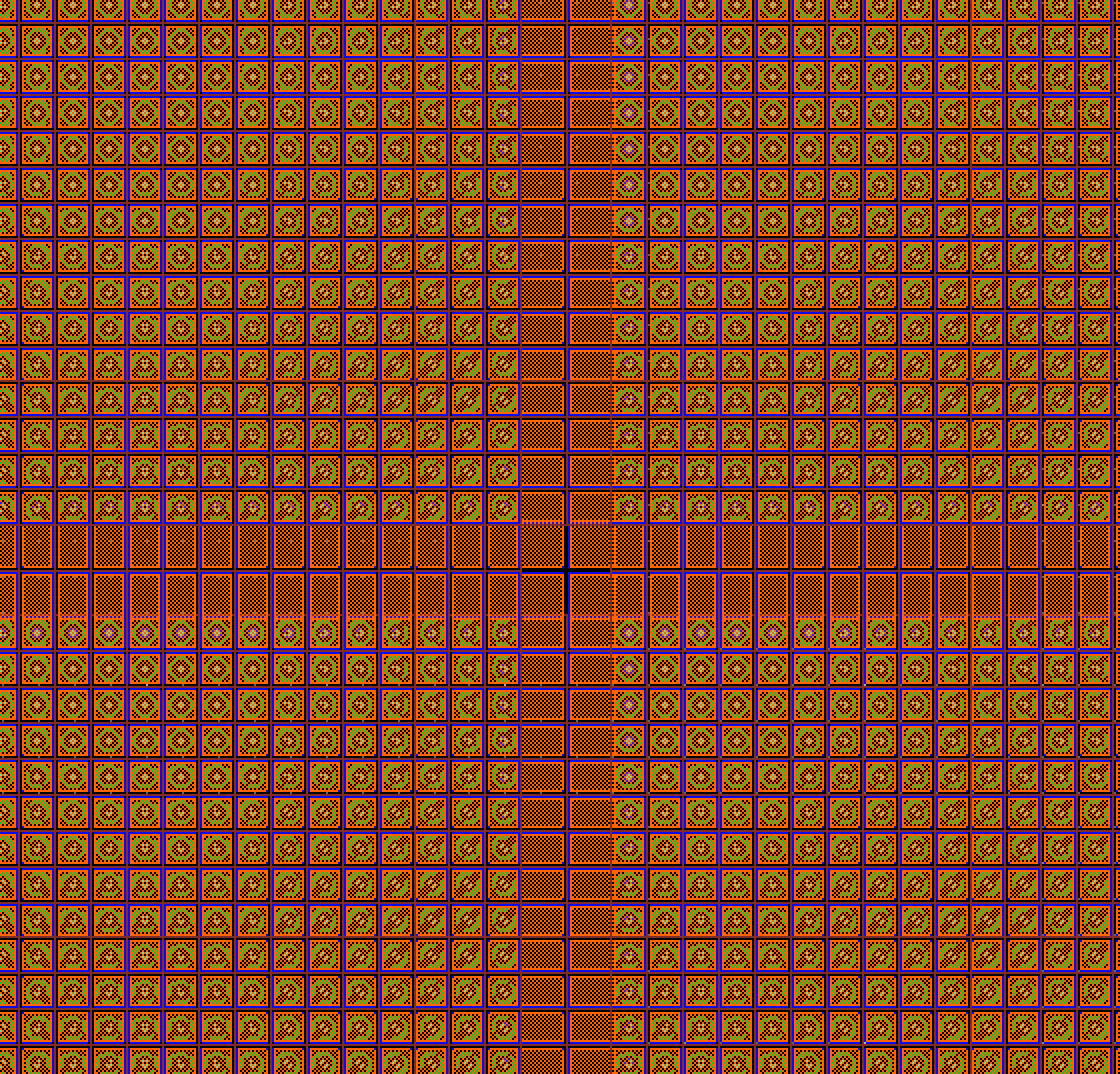
- sensor regular pixel size 100x100 µm²,
- shown on plot gap pixels 100x225 µm² and four central pixels 225x225 µm².
- See plot for composite detectors in EPIX10KA2M and EPIX10KAQUAD
Configuration objects for epix10ka
Python psana has currently defined a few configuration objects for epix10ka:
| Code Block | ||||
|---|---|---|---|---|
| ||||
  co.acqToAsicR0Delay                 co.asicMask                         co.calibPixelConfigArray            co.numberOfCalibrationRows          co.scopeEnable
  co.adcClkHalfT                      co.asicPixelConfigArray             co.calibrationRowCountPerASIC       co.numberOfColumns                  co.scopeTraceLength
  co.adcPipelineDelay                 co.asicPpbe                         co.carrierId0                       co.numberOfEnvironmentalRows        co.scopeTrigChan
  co.adcPipelineDelay0                co.asicPpbeControl                  co.carrierId1                       co.numberOfPixelsPerAsicRow         co.scopeTrigEdge
  co.adcPipelineDelay1                co.asicPpmat                        co.dacSetting                       co.numberOfReadableRows             co.scopeTrigHoldoff
  co.adcPipelineDelay2                co.asicPpmatControl                 co.digitalCardId0                   co.numberOfReadableRowsPerAsic      co.scopeTrigOffset
  co.adcPipelineDelay3                co.asicPPmatToReadout               co.digitalCardId1                   co.numberOfRows                     co.SyncDelay
  co.adcReadsPerPixel                 co.asicR0                           co.enableAutomaticRunTrigger        co.numberOfRowsPerAsic              co.SyncMode
  co.adcStreamMode                    co.asicR0ClkControl                 co.environmentalRowCountPerASIC     co.prepulseR0Delay                  co.SyncWidth
  co.analogCardId0                    co.asicR0Control                    co.epixRunTrigDelay                 co.prepulseR0En                     co.testPatternEnable
  co.analogCardId1                    co.asicR0ToAsicAcq                  co.evrDaqCode                       co.prepulseR0Width                  co.TypeId
  co.asicAcq                          co.asicR0Width                      co.evrRunCode                       co.R0Mode                           co.usePgpEvr
  co.asicAcqControl                   co.asicRoClk                        co.evrRunTrigDelay                  co.scopeADCsameplesToSkip           co.Version
  co.asicAcqLToPPmatL                 co.asicRoClkHalfT                   co.numberOf125MhzTicksPerRunTrigger co.scopeADCThreshold                co.version
  co.asicAcqWidth                     co.asics                            co.numberOfAsics                    co.scopeArmMode
  co.asicGR                           co.asics_shape                      co.numberOfAsicsPerColumn           co.scopeChanAwaveformSelect
co.asicGRControl co.baseClockFrequency co.numberOfAsicsPerRow co.scopeChanBwaveformSelect |
| Code Block | ||||
|---|---|---|---|---|
| ||||
asic.atest asic.FELmode asic.RO_rst_en asic.S2D_tcomp asic.chipID asic.Filter_DAC asic.RowStart asic.Sab_test asic.ColumnStart asic.Hrtest asic.RowStop asic.SLVDSbit asic.ColumnStop asic.is_en asic.S2D asic.tc asic.CompEn_lowBit asic.Monost asic.S2D0_DAC asic.test asic.CompEn_topTwoBits asic.Monost_Pulser asic.S2D0_GR asic.testBE asic.CompEnOn asic.OCB asic.S2D0_tcDAC asic.testLVDTransmitter asic.CompTH_DAC asic.Pbit asic.S2D1_DAC asic.TPS_DAC asic.DelCCKreg asic.PixelCB asic.S2D1_GR asic.TPS_GR asic.DelEXEC asic.pixelDummy asic.S2D1_tcDAC asic.TPS_MUX asic.DM1 asic.PP_OCB_S2D asic.S2D2_DAC asic.TPS_tcDAC asic.DM1en asic.Preamp asic.S2D2_GR asic.TPS_tcomp asic.DM2 asic.Pulser asic.S2D2_tcDAC asic.trbit asic.DM2en asic.Pulser_DAC asic.S2D3_DAC asic.Vld1_b asic.emph_bc asic.PulserR asic.S2D3_GR asic.VREF_DAC asic.emph_bd asic.PulserSync asic.S2D3_tcDAC asic.VrefLow asic.fastPP_enable asic.RO_Monost asic.S2D_DAC_Bias |
Gain coding
Data gain bits assignment
2018-02-23 Gabriel:
Each pixel value is represented over 16 bits; the lowest 14 bits (0 to 13) encode the 14-bit ADC value, and bit 14 encodes the gain mode as either High (bit14==1) or Medium/Low (bit14==0) !!! THIS IS WRONG. SHOULD BE bit14==1/0 for L/H,M !!!. The choice between Medium and Low is determined globally for the ASIC by the asic.trbit.
Gain modes (Fixed High/Medium, Fixed Low, Auto High/Medium to Low, Forced High/Medium to Low, Masked) are determined per pixel; this information is required for reconstruction and is presumably saved in the metadata (the various modes have somewhat different pedestals, for example).
In practice the whole pixel matrix is most likely to be programmed with the same pattern, i.e., gain mode. While we had a philosophical discussion on using bit 15 for providing more info, due to the asynchronous way the pixel configuration mask is programmed, there is a lot of potential for confusion, so now bit 15 is not used.
2018-02-26 26 email from Faisal:
1) Just to elaborate a bit more, trbit is not part of the pixel config. It is part of the ASIC config just like atest, CompEn, etc. Your statement is correct it is defined per ASIC not camera.
...
Bit coding is as follows: MSB to LSB
Pixel Mask
ga g M Tx x 1 x pixel is maskedx x 0 1 pixel is under test0 0 x x auto switch0 1 x x force switch1 0 x x low gain (fixed)1 1 x x high gain (fixed)For example
0x0 for all pixel is auto switch. If tr=1, then auto switch high to low, if tr=0 then auto switch medium to low. Please note trbit is not part of the pixel config.
...
If you want to test a pixel e.g. run the internal pusler then AND its config with 0x1.
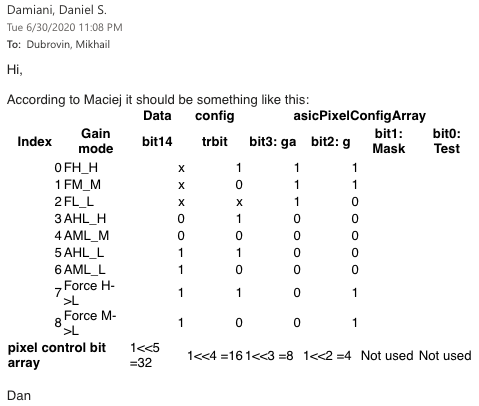
2020-06-30 Dan and Maciej about forced gain modes
Calibration rows
Each ASIC has (176+2 rows x 192 columns), the last two rows are the calibration rows. These rows are not connected to the sensor and are constructed without a pixel/sensor interface. They will be powered just like any other pixel in the ASIC, therefore, they see similar voltages, noise, etc just like other pixels.
# psana returns 4 rows: r0, r1, r2, r3
wirebonds
wirebonds#|||||||||##¯¯¯¯|¯¯¯¯## A2 | A1 ##----|----## A3 | A0 ##____|____##|||||||||# wirebonds
wirebonds# r0 is row 176 in ASIC0 and ASIC3
...
# when pxiel (ga,g ,M,T) is xx1x then 176 is pixel max and 177 is baseline
Calibration files for dark
2018-02-28 Philip:
"force switch" mode: the camera starts high then goes low - this simulates switching.
This mode should be used for calibration of pedestals for switched mode.
I think by the way that we need to have two pedestal files in standard running:
H/M (dark)
H/M->L (forced)
In the case where we run the array in H/M/L without auto-ranging, we can
just populate the relevant pedestals.
H/M (dark)
H/M->L (forced)
In the case where we run the array in H/M/L without auto-ranging, we can
just populate the relevant pedestals.
2018-02-28 Angelo:
The force switch mode should be ignored. It is a debugging mode that should not be used for calibration.
Gabriel can explain how to do the calibration if needed
Raw data
| Code Block | ||||
|---|---|---|---|---|
| ||||
Command: find_detector_runs MFX epix10ka

    # mfxx32516: nruns 3-377, MfxEndstation.0:Epix10ka.0, MfxEndstation.0:Epix10ka.1
# mfxx36916: runs 1-84, MfxEndstation.0:Epix10ka.1 |
| Code Block |
|---|
dataset    exp=mfxx32516:run=377
calibDir: /reg/d/psdm/MFX/mfxx32516/calib
det.source      : Source("MfxEndstation.0:Epix10ka.0")
shape of ndarray: (352, 384) |

Gain correction files
On 2018-06-20 Gabriel generated gain and offset files in
| Code Block | ||||
|---|---|---|---|---|
| ||||
Camera1-AHL-H-Gain.txt
Camera1-AHL-L-Gain.txt
Camera1-AML-L-Gain.txt
Camera1-AML-M-Gain.txt
Camera1-FH-H-Gain.txt
Camera1-FL-L-Gain.txt
Camera1-FM-M-Gain.txt |
Archived in /reg/g/psdm/detector/gains/epix10k/2018-06-04-Camera1/
| Code Block | ||||
|---|---|---|---|---|
| ||||
          Gain             Offset
          Mean   RMS       Mean   RMS
-------------------------------------------------------
FL-L      1.28   0.06         0     ?
FM-M     42.43   2.00      2331   150
FH-H    128.49   6.17      2354   151
AML-L     1.26   0.06      2115   164
AML-M    42.52   1.92      2334   150
AHL-L     1.29   0.06      2119   190
AHL-H   128.72   6.03      2358   151
------------------------------------------------------- |
Control bits table
| Code Block | ||||
|---|---|---|---|---|
| ||||
    #--------------------------------
    #   data bit 14 is moved here 1/0 for H,M/L
    #  / trbit  1/0 for H/M
    # V / bit3  1/0 for F/A
    #  V / bit2 1/0 for H,M/L
    #   V / M  mask
    #    V / T  test       gain range index
    #     V /             /  in calib files
    #      V             V
    # x111xx =28 -  FH_H 0
    # x011xx =12 -  FM_M 1
    # xx10xx = 8 -  FL_L 2
    # 0100xx =16 - AHL_H 3
    # 0000xx = 0 - AML_M 4
    # 1100xx =48 - AHL_L 5
    # 1000xx =32 - AML_L 6
    # 1101xx =49 - AHL_FL 7
    # 1001xx =33 - AML_FL 8
#-------------------------------- |
| Data | config | asicPixelConfigArray | |||||
|---|---|---|---|---|---|---|---|
| Index | Gain mode | bit14 | trbit | bit3: ga | bit2: g | bit1: Mask | bit0: Test |
| 0 | FH_H | x | 1 | 1 | 1 | ||
| 1 | FM_M | x | 0 | 1 | 1 | ||
| 2 | FL_L | x | x | 1 | 0 | ||
| 3 | AHL_H | 0 | 1 | 0 | 0 | ||
| 4 | AML_M | 0 | 0 | 0 | 0 | ||
| 5 | AHL_L | 1 | 1 | 0 | 0 | ||
| 6 | AML_L | 1 | 0 | 0 | 0 | ||
| 7 | AHL Forced L | 1 | 1 | 0 | 1 | ||
| 8 | AML Forced L | 1 | 0 | 0 | 1 | ||
| pixel control bit array | 1<<5 =32 | 1<<4 =16 | 1<<3 =8 | 1<<2 =4 | Not used | Not used | |
Gain correction formula
corrected = (raw - pedestals)/gain
Anchor MeetingWithGabriel MeetingWithGabriel
Common mode correction
| Anchor | ||||
|---|---|---|---|---|
|
Added on 2020-06-04.
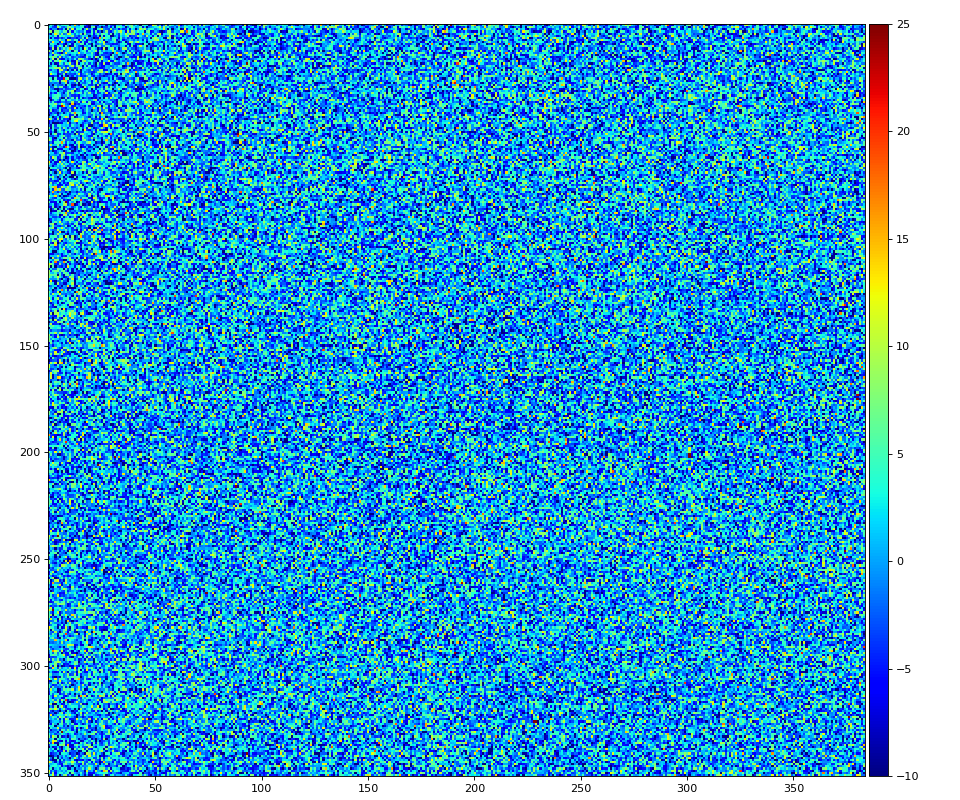
The value (raw - pedestals) can be corrected for common mode effect.
First image below shows one epix10ka segment non-corrected image of shape (352, 384). Vertical stripes presumably arising from this hardware effect.
The same median algorithm is applied as for Jungfrau, but separately for up- and down- part of the segment with parameters
cmpars=(<algorithm-id>, <mode>, <maximal-correction>), where
- algorithm-id is not used
- mode=0 - no correction, bit1=1 - in rows (is not useful for epix10ka), bit2=1 - in columns (the best for epix10ka)
- maximal-correction - maximal allowed correction in ADU
NOTE: currently mask on gain mode is not applied - all pixels are used to evaluate and correct for offset.
Examples of the command to get corrected image:
nda_cdata = det.calib(evt, cmpars=None) # default - cm pars from calib directory/system
nda_cdata = det.calib(evt, cmpars=(0, 0, 100)) # use cmpars, do not apply cm correction
nda_cdata = det.calib(evt, cmpars=(0, 2, 100)) # use cmpars, apply cm correction in columns
Images before and after common mode correction:

Meeting with Gabriel
On 2018-07-06 15:13 meeting with Gabriel.
Summary:
- control bit table is correct
- formula should include pedestals in stead of offset
- pedestals need to be generated and saved as txt file of shape (7, 1, 352, 384) under calib directory, for example:
/reg/d/psdm/MFX/mfxx32516/calib/Epix10ka::CalibV1/MfxEndstation.0:Epix10ka.0/pedestals/0-end.data - Gabriel on pedestal calibration:
- offsets and gain are calibrated not very often (say, once per month...)
- pedestals should be calibrated pretty often (once per hour...)
- pedestal calibration is implemented in AMI, using offsets,
- script works on dark runs accumulated for 5 gain modes
- + 2 gain modes are evaluated using combination of other 2 and offsets
- pedestal calibration procedure needs to be completed.
Calibration Details
See this page: https://confluence.slac.stanford.edu/display/ppareg/ePix10K+Calibration
Per panel calibration constants
Algorithm for xtc data with charge injection processing is developed by Gabriel and is wrapped in psana environment as CLI
Detector/app/epix10ka_offset_calibration
Similarly, dark run processing script is
Detector/app/epix10ka_pedestals_calibration
These commands will be available in releases > ana-1.3.58. See description using option "-h", e.g.
command> epix10ka_offset_calibration
command> epix10ka_pedestals_calibration
File naming convention in panel calibration repository
/reg/g/psdm/detector/gains/epix10k/panels/ - default repository <dir-repo>, can be re-directed for test by option "-o <dir-name>".
<dir-repo>/3791847426-0170080513-1879048214-0191557724-0003673288-2996154369-0218103833/,
Sub-directories for each panel:
offsetpedestalsplotsworkgain# content will be provided by Philip
<dir-repo>/.aliases.txt
<dir-repo>/panels/logs/
Panel calibration file name: epix10ka_0001_20180514120622_mfxx32516_r1021_pedestals_AHL-H.dat, where
epix10ka - detector type0001- panel id alias as specified in/reg/g/psdm/detector/gains/epix10k/panels/.aliases.txt20180514120622- run start time stamp in format '%Y%m%d%H%M%S'mfxx32516_r1021- experiment and run for production of this constantspedestals- constants typeAHL-H- gain range (mode)
File with already processed arrays is saved as
<dir-repo>
with extra fields in name sp02 for charge injection spacing number of pixels.
Constants merging for multi-panel detectors
command> epix10ka_deploy_constants -h
shows description of command line options. This command with sufficient number of parameters (at least experiment, run, and detector name)
- combines gain mode and panel calibration files in arrays of shape (7, <number-of-panels>, 352, 384)
- deploys calibration files in the calib directory, e.g.
/reg/d/psdm/MFX/mfxx32516/calib/Epix10ka::CalibV1/MfxEndstation.0:Epix10ka.0/pixel_gain/0-end.data
/reg/d/psdm/MFX/mfxx32516/calib/Epix10ka::CalibV1/MfxEndstation.0:Epix10ka.0/pedestals/0-end.data
Pedestal Deployment Meeting Notes (8/2/18)
- script that is use to drive the daq with hutch python: /reg/g/pcds/pyps/mfx/dev/mfx/experiments/mfxls3416.py
- for epix, 5 gain ranges (3 fixed, 2 auto) generate 7 pedestals
- maybe have "all range" option, and fast "selected ranges" option.
- maybe "all range" at beginning of expt, but "selected ranges" during expt.
- jason thinks medium/low is the default
- in the "selected ranges" mode makepeds will reuse the current numbers for ranges that weren't selected.
- multi-panel epix10k should be the same as jungfrau (might need to massage
- the daq appropriately)
- mikhail/gabriel: data processing call in makepeds script
- silke/jason/dan: hutch python, makepeds wrapper
- /reg/g/pcds/engineering_tools/R1.2.9/scripts/makepeds calls makepeds_psana calls mikhail's stuff (jungfrau_ndarr_dark_proc)
List of known detectors on 2018-11-12
command> find_detector_names
| Code Block |
|---|
#== type 0022 epix10ka
               'DetLab.0:Epix10ka.0': 'epix10ka_0000',\
     'MecTargetChamber.0:Epix10ka.0': 'epix10ka_0001',\
     'MecTargetChamber.0:Epix10ka.1': 'epix10ka_0002',\
        'MfxEndstation.0:Epix10ka.0': 'epix10ka_0003',\
        'MfxEndstation.0:Epix10ka.1': 'epix10ka_0004',\
'MfxEndstation.0:Epix10ka.2': 'epix10ka_0005',\ |
Composite detectors
EPIX10KA2M and EPIX10KAQUAD - composite detectors made of epix10ka panels.
References
- https://github.com/slaclab/cac/tree/master/psana/epix10ka - scripts from Faisal
- https://pswww.slac.stanford.edu/apps/portal/index.php?exper_id=1107 - under Workflow -> Batch Processing - batch processing
- /reg/d/psdm/MFX/mfxx32516/results/abunimeh/2 - experimental and jupyter notebook scripts
- ePix10K Calibration, by Gabriel Blaj
- EPIX10KA2M and EPIX10KAQUAD
- Jungfrau and Epix10ka Calibration
- 2021-09-28 learn about existence of presentation 2019-10-02-ePix10K-500um-Sensor-Geometry.pdf
...
Overview
Content Tools