...
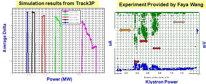
Left figure is the calculated multipacting bands, the right is the measured electron pickup and vacuum signals after initial processing. Table lists the power levels for the occurrences of different multipacting bands. The klystron and coupler powers monitored during experiments are different because of attenuation in the setup.

MP simulation on coax with reflection
During the transient of cavity filling, the input power is partially reflected which forms a partial standing wave in the coupler. The transient reflection ranges from 1 to 0 in the matched case. Thus it is instructive to investigate how the multipacting behaviors in the coupler change with finite reflections. This slide shows the multipacting maps for the cold coax indicating the dependence of multipacting order on the power level for the cases with reflection coefficient 0 and 0.5, respectively. In general, the multipacting order decreases at higher power levels. When a partial standing wave exists in the coax, multipacting is shifted towards lower orders and lower power levels. This figure shows a multipacting trajectory for the reflection of 0.5. It is a 5th order multipacting event at the power level of 160 KW, ans has an impact energy of 543 eV which falls in the enhancement portion of the SEY curve for niobium