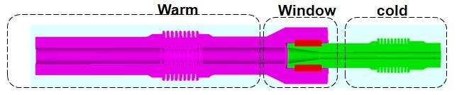
The TTF-III power coupler adopted for the ILC baseline cavity design has shown a tendency to have long initial high power processing time. A possible cause for the long processing time is believed to be multipacting in various regions of the coupler. To better understand the rf processing limitations of the coupler, SLAC, in collaboration with LLNL, has built a flexible high-power test stand. The coupler comprises of different components including the cold/warm coaxes, the cold/warm bellows and the ceramic window separating the cold and warm sides. To corroborate with experimental measurements, Track3P has been used to numerical simulate of multipacting for individual components.

MP simulation on cold coax
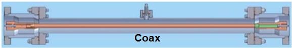
The first component of the TTF-III power coupler tested for high power processing is the cold coax, This fig shows a model of the coax in the experimental setup,
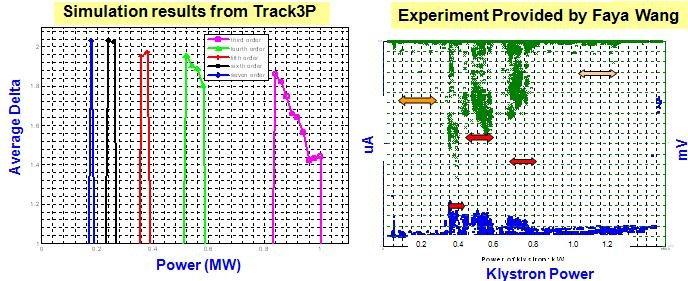
Left figure is the calculated multipacting bands, the right is the measured electron pickup and vacuum signals after initial processing. Table lists the power levels for the occurrences of different multipacting bands. The klystron and coupler powers monitored during experiments are different because of attenuation in the setup.

MP simulation on coax with reflection
During the transient of cavity filling, the input power is partially reflected which forms a partial standing wave in the coupler. The transient reflection ranges from 1 to 0 in the matched case. Thus it is instructive to investigate how the multipacting behaviors in the coupler change with finite reflections. This slide shows the multipacting maps for the cold coax indicating the dependence of multipacting order on the power level for the cases with reflection coefficient 0 and 0.5, respectively. In general, the multipacting order decreases at higher power levels. When a partial standing wave exists in the coax, multipacting is shifted towards lower orders and lower power levels. This figure shows a multipacting trajectory for the reflection of 0.5. It is a 5th order multipacting event at the power level of 160 KW, ans has an impact energy of 543 eV which falls in the enhancement portion of the SEY curve for niobium see TTFIIIcoaxreflection.pptx
MP simulation on cold coax bellow
Multipacting simulation is sensitive to the local fields on the boundary. It is important to model the geometry accurately around the curved surfaces and high field regions, e.g. the disk iris and the disk slots in the HDX structure. Finite element methods allow the use of local mesh refinement and higher order curved elements around curved surfaces for better solution accuracy
The simulation of the cold bellows region includes the cold bellows and the coas at both ends because the coas is required for the propagation of a travling wave. There were no multipacting activites observed in the bellows region up to 1 MV of input power. The up plots shows electron distributions at the 2nd and the 100th rf period. No electrons ?survived? longer than 100 rf periods in the bellows region, but multipacting activities remain in the upstream and downstream coax regions. This plot shows a multipacting trajectory for the reflection of 0.5. It is a 5th order multipacting event at the power level of 160 KW, and has an impact energy of 543 eV which falls in the enhancement portion of the SEY curve for niobium.TTFIIImachinemodel.jpg
MP simulation on ceramic window
Plots shows the electric field pattern in the region near the ceramic window. Because of the lack of measured data on secondary emission yield of ceramic surface, we cannot use the SEY enhancement factor to quantify multipacting events. Instead we use the impact energy to indicate multipacting activities when resonant trajectories are detected. This plot shows the impact energy and MP order versus input power for two point multipacting particles between ceramic window and cold inner conductor. A 2-point 2nd order multipacting event is shown between the ceramic window and the inner conductor on the cold side. TTFIIIceramicwindow.pptx