...
Layout of the LCW system feeding the DPS pumps
Cooling water for the DPS system is provided by the same LCW water that cools the magnets.
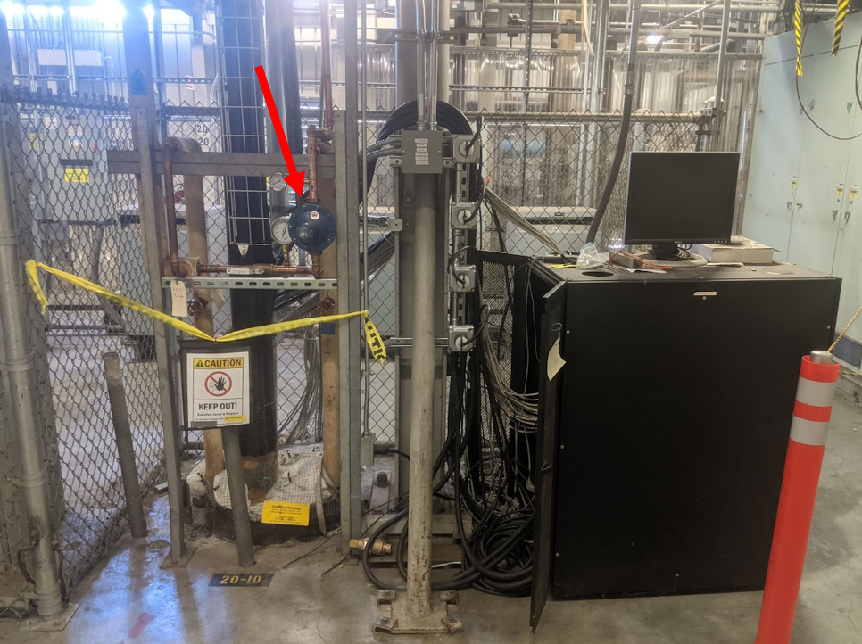
The DPS pumps require the LCW water pressure to be reduced from nominal LCW pressure of ~180psi to around ~60psi. This is done by a pressure regulator in the gallery at penetration 20-10 - pointed at in the image below. The water is transported down the penetration through the insulated pipe. Note that the inline valve to the lower left of the regulator should be open.
In the tunnel at Pen. 20-10, the water is split off towards the upstream and downstream DPS systems.
Image coming soon...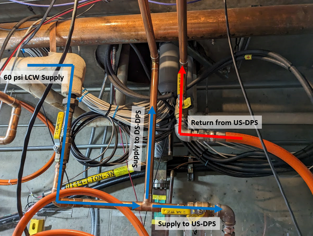
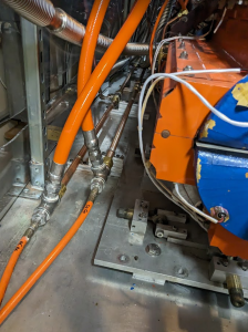
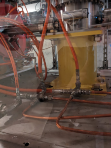
Water flows in parallell to each of the turbos/roughing pumps on each side of the DPS, flowing from a supply manifold, through the pumps, then back to the return manifold. Upstream and downstream manifolds are shown below.Image coming soon...
The return feeds back into the main return water manifold on the tunnel ceiling.Image coming soon...
Related articles
| Content by Label | ||||||||||||||||||
|---|---|---|---|---|---|---|---|---|---|---|---|---|---|---|---|---|---|---|
|
...