Page History
...
At first stage pixels in the good range (as shown in table) are selected.
value | min | max | good range |
|---|---|---|---|
| offset | 0 | <data-bits> | (min, max) |
| gain | 0 | <data-bits>/10 | (min, max) |
| chi2 | 0 | unlimited | (min, max) |
| neg | 1 | 3 | [min, max] |
Then, for each array (except neg) pixels in good range two median values are evaluated,
...
are considered as good, while other marked by the status bit status in . the pixel_status_ci array, with summary table printed at the end of the job,
...
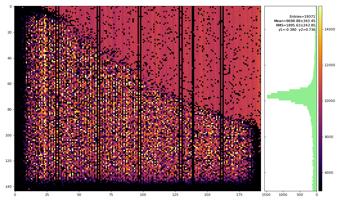
AML-M plots for offset, gain, and chi2 chi2
Images corresponds to --slice "0:144,0:192" single ASIC of total panel shape:(288, 384).


Summary
- Charge charge injection processing for epixhr is nearly ready
- test 1-ASIC panel contains a lot of dead and noisy pixels
- H and M gain modes shows significant non-linearity
- Q: what to save and how to apply constants
Questions
- pixel status is evaluated for this procedure
- fit results in terms of offset and gain constants are saved along with chi2 and pixel status arrays
- Philip: at 1st stage this script will be used for detector characterization
- pedestals are not re-evaluated
- gains are not used directly
- What fit parameters should be saved? (offset and gain)
- Formula to apply pedestals, offset and gain for intensity correction
References
...
Overview
Content Tools