...
| Code Block |
|---|
cd /home/itkpix/optoboard-system/optoboard_felix python quick_startInitOpto.py -optoboard_serial 00000000 -vtrx_v 1.3 -sflx_G 000000000 -Gflx_d 0 -dconfigure 01 |
The -soptoboard_serial specifies the serial number used (00000000 is the default one for Optoboard V2.1), -flx_G is the link group number of FELIX and -flx_d the FELIX device. The option -configure set to 1 will configure all lpGBTs, if set to 0 will configure only the master. If -soptoboard_serial is set to 00000000 and -vtrx_v 1.3, optoboard_felix sends the parameters in the config ~/optoboard_felix/configs/optoboardoptoboard2_lpgbtv1_gbcr2_vtrxv1_3_default.json to the lpGBTs, GBCR and VTRx+. Check the FELIX documentation or the optoboard_felix readme for more information on this. If this succeeded, the single optoboard LV current will go up to ~900mA.
...
In case any present link got power below 700uW, please check the VTRX+ fiber pigtail ferrule junction to the MPO splitter is fully plugged in. You can further check the optoboard configuration for link speed, tracking mode and link locking phase by running InitOpto.py with the python script: additional option -i which starts an interactive python session after configuration and defines an opto object that can be probed for various settings (see full API documentation for details):
| Code Block |
|---|
cd /home/itkpix/optoboard-system/optoboard_felix python opto_doc.py - -i InitOpto.py -optoboard_serial 00000000 -vtrx_v 1.3 -s 00000000 -flx_G 0 -d 0flx_d 0 -configure 1 >>> opto.bertScan(...) # perform BERT scans >>> opto.opto_doc() # Print status information on all lpgbts (equivalent to following functions for lpgbt1) >>> opto.lpgbt1.check_PUSM_status() # check power up state machine state (int 0-19 see ch 8.1 of lpgbt manual, 19=ready) >>> opto.lpgbt1.check_lpgbt_config_pins() # check hardware configuration >>> opto.lpgbt1.check_EPRX_status() # check elink uplink status for all channels (enabled, rate, polarity, phase) >>> opto.lpgbt1.check_EPRX_locking() # check phase locking |
After fibre fanout installation:
After the fibre fanout is installed, configuring the Optoboards will look similar to this:
| Code Block |
|---|
python quick_startInitOpto.py -optoboard_serial 00000000 -vtrx_v 1.3 -sflx_G 000000000 -Gflx_d 0 -dconfigure 1 0 python quick_start.py - InitOpto.py -optoboard_serial 00000000 -vtrx_v 1.3 -s 00000000 -flx_G 1 -flx_d 0 -configure 1 python quick_startInitOpto.py -optoboard_serial 00000000 -vtrx_v 1.3 -s 00000000 -flx_G 2 -flx_d 0 -configure 1 python quick_startInitOpto.py -optoboard_serial 00000000 -vtrx_v 1.3 -s 00000000 -flx_G 3 -flx_d 0 -configure 1 |
Or with the separate configs that are created in ~/optoboard_felix/configs:
| Code Block |
|---|
python quick_startInitOpto.py -vtrx_v 1.3 -c /configs/2400003.json python quick_startInitOpto.py -vtrx_v 1.3 -c /configs/2400006.json python quick_startInitOpto.py -vtrx_v 1.3 -c /configs/2400007.json python quick_startInitOpto.py -vtrx_v 1.3 -c /configs/2400011.json |
...
During the startup of the digital calibration, the module configuration would increase the ITkPixV1.0 SCC current to 4.38A (frofrom, 3.07A). The calibration results are kept at /home/itkpix/YARR-FELIX/data/. Successful calibration should have an output Root file.
...
*after power-up and inside the test-Optopanel with 9.0 V supplied. If powered outside the test-Optopanel directly on the connector with 2.5 V expect a current ~415 mA.
| History | Comments |
|---|---|
| 2400011 | Resistor R108 removed Oct/2022 to debug FELIX FEC12 mode problem. R108 back on Feb/2023. |
Connectors:
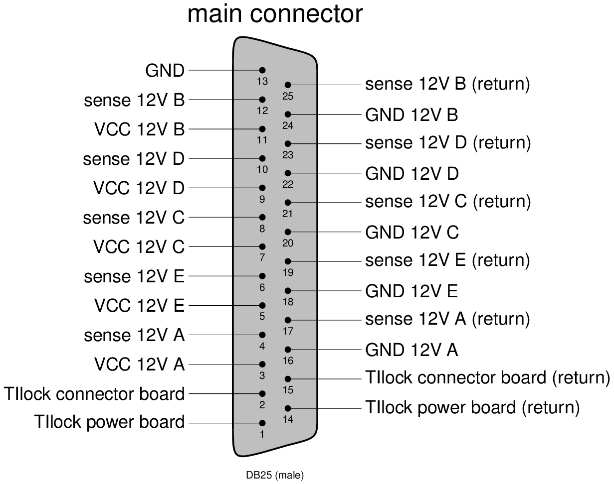
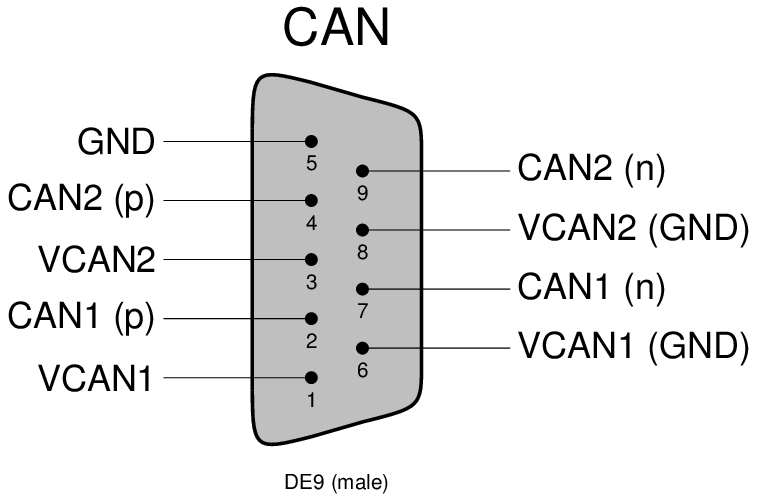
Check the above interfaces document for more detailled description.
...
The initial single optoboard setup used for the early SLAC tests with single chip cards is summarized in the diagram below:
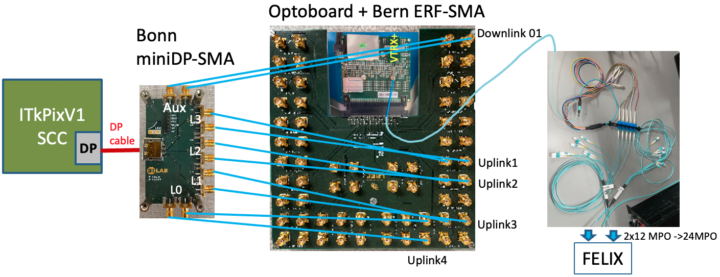
| Bonn miniDP-SMA | Bern ERF-SMA | lpGBT |
|---|---|---|
| AUX | DOWNLINK 01 | 1 |
| LN3 | L1 UPLINK 01 | 1 |
| LN2 | L1 UPLINK 02 | 1 |
| LN1 | L1 UPLINK 03 | 1 |
| LN0 | L1 UPLINK 04 | 1 |
Each fiber in the pigtail corresponds to data coming from a separate lpGBT (verification needed for RX 3 and 4):
...
There is a broken connection in L1 UPLINK 02 in the ERF-SMA board or within the optoboard itself. Note that alignment is sensitive to polarity of TX connection (i.e. NP↔NP vs NP↔PN) but not to the RX connections.
Some Useful Links
- Optoboard System Documentation
- FELIX JIRA (Oct/22) on optoboard + ITkPix readout setup
- CERN mattermost Bern-Optoboard channel
- Talk (Dec/9/2022) by Angira Rastogi on Optoboard-FELIX setup at LBNL
...