Design and Layout of LSS
PLC Installation
Module Installation
...
- Connect 28-pin cable (circled in blue) from each input/output module to its corresponding input/output terminal block.
- Connect cable from 15-pin port on PLC module (circled in orange) to 9-pin port on RS232 converter (pictured below).


- Wire positive and negative terminals (circled in green) to those of the Quint Power Supply Unit (pictured below).
Installing and Connecting Breakout Modules


Connect cable from terminal block on relay module (above) to pinout on relay (below).


Power
- Wire the + and - terminals on top of the unit to the 24V and GND Phoenix contacts
- The cable from underneath the Quint Power Supply Unit may then be connected to a power source.
...
- Download the software installer from https://support.automationdirect.com/products/directsoft.html.
- Install the latest version of DirectSoft.
- License Key: QKGD-6L68-Y019-J117
Connecting to the PLC
- Plug HDMI cable into Port 1 (circled) of PLC module.
- USB adapter will be needed to connect to computer.
- PLC must be in terminal mode ("TERM") to transfer changes.
- In the DirectSoft program, navigate to the toolbar and click the dropdown menu labelled “PLC”.Select "Connect..."go to PLC > Connect...
- If the PLC has never been connected to the computer before, create link.
- In the “Select Link…” pop-up window, click “Add…”Select Link... > Add...
- Select the communications port that the PLC is connected to.
- This may be found in the Device Manager of your computer’s Control Panel
- Select the PLC’s product family.
- Example: DirectLogic205 will be from the DL 0/1/2/4/350 Family
- Select the protocol to use in the communications link.
- SLAC LSS uses K Sequence
- Address: 1
- In the “Select Link…” pop-up window, click on the PLC you are using and press “Select”.
Port Settings
...
- Navigate to the toolbar and click the dropdown menu labelled "PLC". Roll-over "Setup" and select "PLC > Setup > Setup Sec. Comm Port..." from the dropdown menu.
- Settings
- Port 2
- Non-Seq(ASCII)
- Base Timeout
- Data bits: 8
- Baud rate: 9600
- Stop bits: 1
- Parity: None
- Memory address: V7000
- Write the new settings to the PLC by clicking the icon:

Common Program Rungs
- Standard Order of Code
- Reset all variables
- Set necessary variables
- Shutter section
- Interlocks and latches
- Mode changes inhibited
- Logic section
- Bypasses
- Mode selection
- In order from the mode with the least privileges to the mode with most privileges
- Lights
- Signs
- End
- Alternating On/Off
- For blinking lights, special buzzer patterns, etc.
- Example code (for use with EO buttons):

- Signs
- PRINT Box
- Port: K2
- Script example: “_00_00_00_00_00_01Z00_02A0_1B b_1A9_1C1LASER IMMINENT _04”
- Start of header
- “_00_00_00_00_00
- Define sign address
- Broadcast to all signs: _01Z00
- Message for signs with specific address: _01Z01, _01Z02, _01Z03, etc.
- Start of text string
- _02A0
- Text dynamics
- Scrolling: _1B a
- Static: _1B b
- Text height
- _1A#
- may be 1-9, with 9 being full height
- Text color
- Red: _1C1
- Green: _1C2
- Yellow: _1C3
- Write message text
- Example: LASER IMMINENT
- End string
- _04"
- Start of header
- Only send print command to sign once
- Reset print command immediately after setting
- PRINT Box
...
- Mounting and Connecting to Power
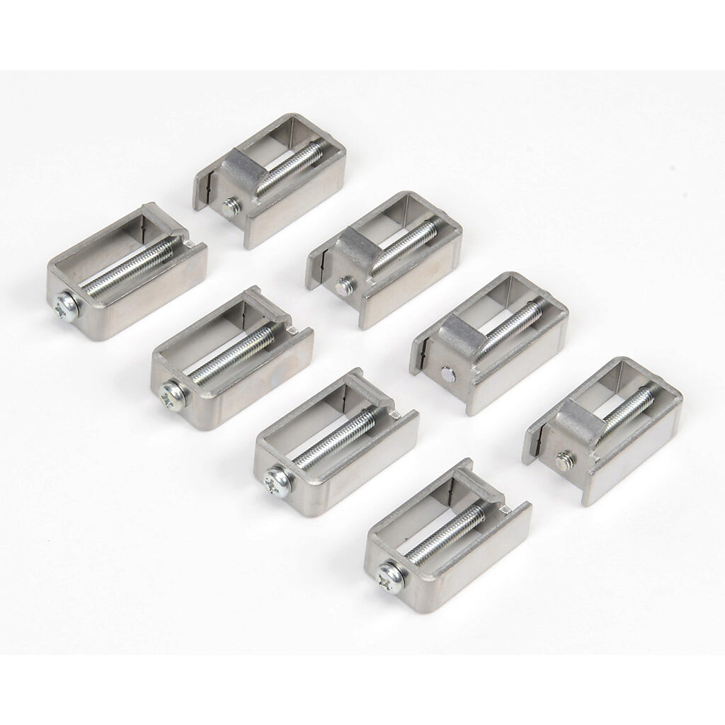
- The C-more touch panel order with come with the touch screen, mounting clips, and a terminal block.
- Use the mounting clips (pictured below) to secure the panel, from the inside, to LSS box door.
- Secure terminal block to back of panel.
- Connect one black wire (GND) from the ground terminal to grounded contact on rack.
- Ground terminal is second from the bottom and will be labelled with the ground symbol.
- Connect one blue wire (power) from the negative terminal to 24V contact on rack.
- Negative terminal is third from the bottom and will be labelled with a minus sign.
- Connecting to the PLC
- Connect HDMI cable from 15-pin port on back of panel to Data Communications Module port (pictured below).
- Connect HDMI cable from 15-pin port on back of panel to Data Communications Module port (pictured below).
- Connecting to Computer
- To upload new code, connect USB Cable from port on back of panel to port on computer.
...
- Download the C-more software
- https://www.automationdirect.com/support/software-downloads?itemcode=C-more%20EA9%20Series
- NOTE: some existing LSS still use EA7
- License Key: 7UGA-R9M6-3FKY-6TQV
- https://www.automationdirect.com/support/software-downloads?itemcode=C-more%20EA9%20Series
- Connect to the PLC
- In C-more, go to Setup > Panel Manager.
- Choose the panel type as labelled on the back of the panel.
- Under COM Port1, click DEV001
- PLC Protocol: AutomationDirect Modbus
- Baud Rate: 9600
- Parity: odd
- Stop Bit: 1
- Transfer a program to the panel
- File > Project Transfer... > Transfer
- Or click the "Send" icon at the top of the window
Programming Common Objects
...
*subject to variability between hutches/components
LED Signs
EO Buttons


- P/N: XW1E-LV
- Connect 24V wire to terminal 4 and input signal wire to terminal 3.
- Connect 24V wire to X1 and output signal wire to X2.
...
Enclosure Interlocks
Stack Light

- 5-pin Cable
- Blue = 24 V
- Black = Input 1 (green)
- Brown = Input 2 (red)
- Datasheet
...