Page History
...
- 2018-11-18-epix10ka2m-metrology-map.pdf
- 2018-11-18-epix10ka2m-metrology-map.pptx
- 2018-11-15-Metrology-epix10ka2m.xlsx
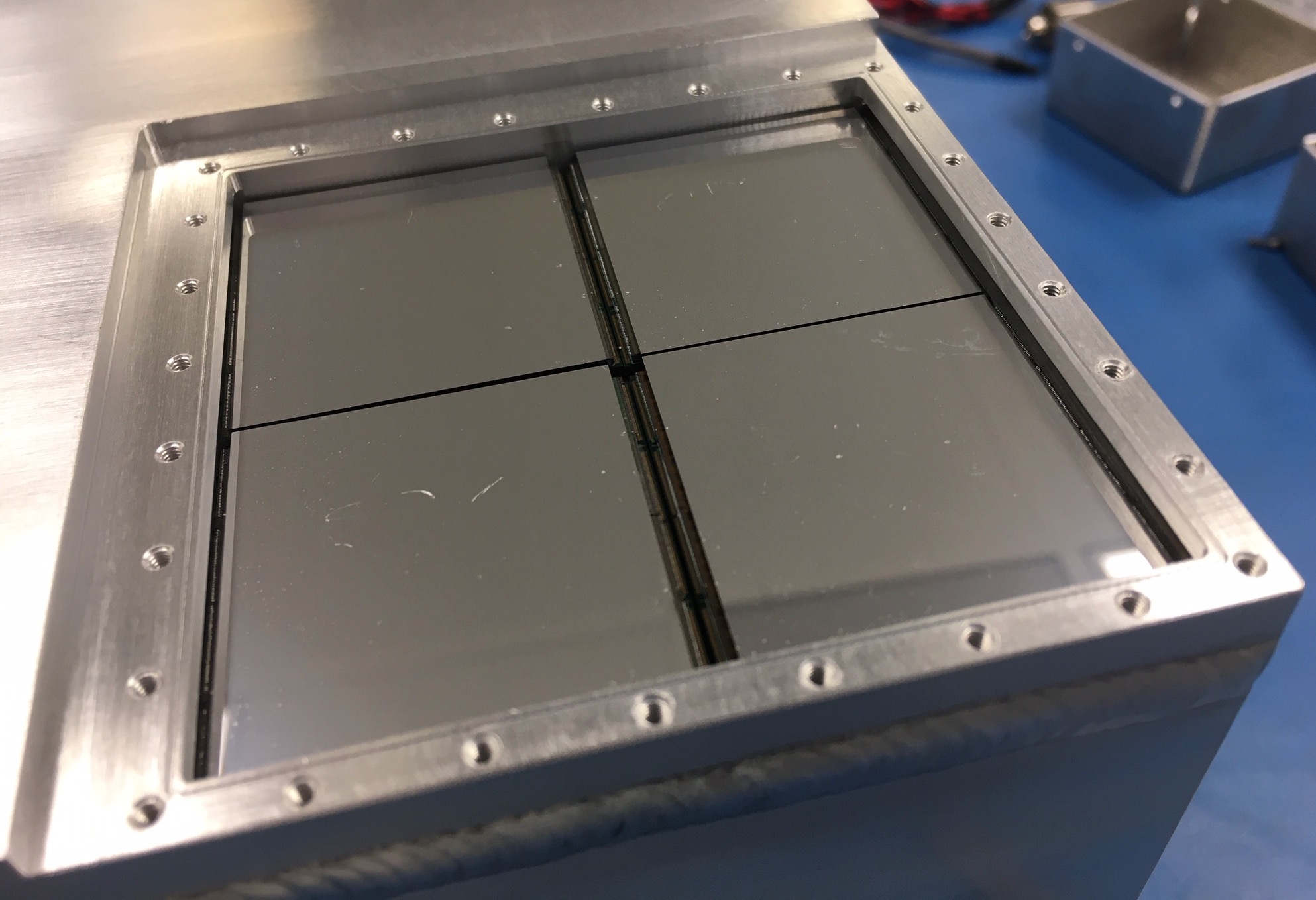
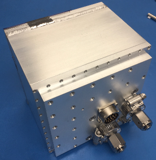
Back side of the new detector epix10ka2m.1 from mfxc00118 2020-07-dd
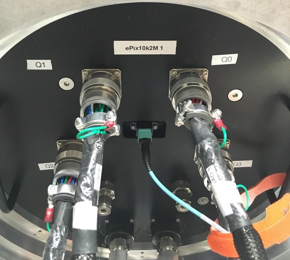
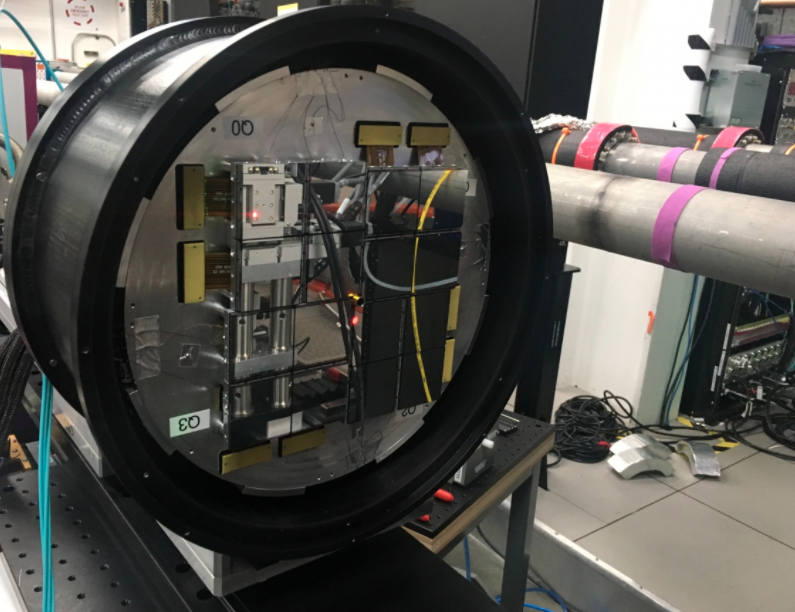
2020-10-06 MEC epix10kaquad 0 front and back
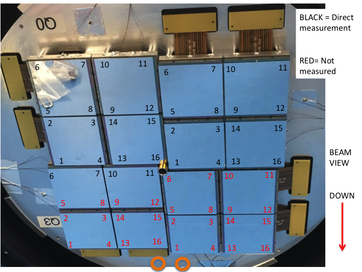
Comments on orientation of epix10ka2m parts from Matt
...
Gain factors from charge injection default and measured
| gain | charge injection | current default | measured (ADU / keV) | 2020-08-03 Gabriel (ADU / keV) - use as default |
|---|---|---|---|---|
| L | 0.46 | 0.01 | 0.139 | 0.164 |
| M | 15. | 0.3(3) | 4.5 | 5.466 |
| H | 46.7 | 1 | 13.9 | 16.40 |
Gain factors default vs charge injection
...
gain from charge injection:
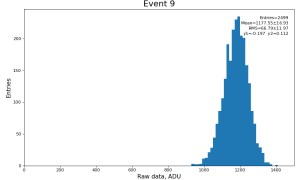
| constants | Mean | RMS | RMS / MEAN |
|---|---|---|---|
| default | 1117.7 | 62.72 | 0.05618 |
| charge injection | 1177.5 | 66.79 | 0.05672 |
Conclusion: in this test charge injection gainci constants do not improve gain factors comparing to default
...
| Code Block | ||||
|---|---|---|---|---|
| ||||
Blaj, Gabriel <blaj@slac.stanford.edu> Mon 8/3/2020 6:52 PM To: Hart, Philip Adam; Dragone, Angelo; Kenney, Christopher J.; Dubrovin, Mikhail; O'Grady, Paul Christopher; Hansson, Conny; McKelvey, Mark E Hi, Here are some good starting values for the ADC to keV conversion: High gain: 132 ADU / 8.05 keV = 16.40 ADU/keV Medium gain: 132 ADU / 8.05 keV / 3 = 5.466 ADU/keV Low gain: 132 ADU / 8.05 keV / 100 = 0.164 ADU/keV Of course, a gain calibration is preferable. The same numbers work in both fixed and auto-ranging gain modes. Thanks, Gabriel ========= Blaj, Gabriel <blaj@slac.stanford.edu> Mon 8/3/2020 7:13 PM Hi, For the long integration time, I don't have a set of magic numbers, but this iterative procedure should yield optimal settings: Cool the camera as low as possible, just a few degrees over the minimum temperature to allow temperature stabilization by the PID control loop (either the chiller PID for the large cameras, or the Peltier PID in the small cameras). Of course, the small cameras can be cooled much lower than the large ones. Start with the default LCLS settings (I believe both AsicAcqWidth and R0toAcq are set to 100us by default) 0 AsicAcqWidth should be optimized for the experiment. With a very cold camera (e.g., < -15ºC) you could go to 5ms. A good starting value would be 1ms. 1 Set AsicAcqWidth to, e.g., 1 ms 2 Set R0toACQ time to 100us 3 Decrease frame rate until no frames are dropped 4 Set the X-ray source to a low flux (0.01-0.05 photons/pixel/frame?) 5 Try to get a uniform illumination 6 Repeat: - Calibrate dark - Take many frames and integrate them - Look if the resulting image is uniform or has a strange sawtooth pattern over each ASIC - If no, try reducing R0toACQ - If yes, try increasing R0toAACQ - Increase/decrease frame rate to the maximum frame rate that runs reliably (no dropped frames). 6 Until an optimum is found. For an idea how the strange sawtooth pattern looks, you could try setting: AsicAcqWidth = 1ms R0toAcq = 50us, or 20us. Thanks, Gabriel |
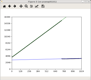
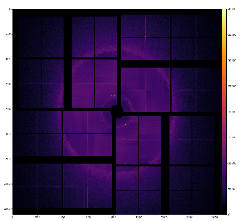
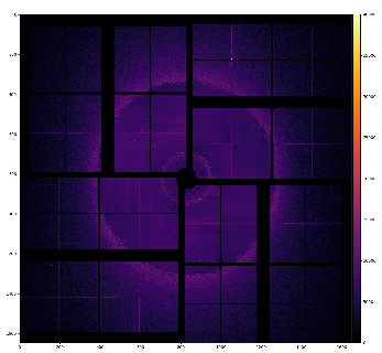
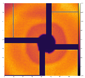
Test of the gain switching modes
...
- AHL: exp=xcsx35617:run=414, event 3
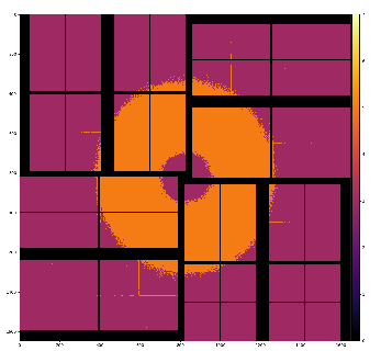
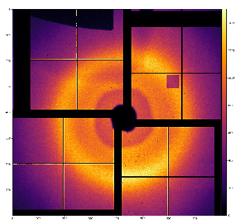
Masks
mask_geo
mask_geo = det.mask_geo(par, mbits=3, width=10, wcentral=5)
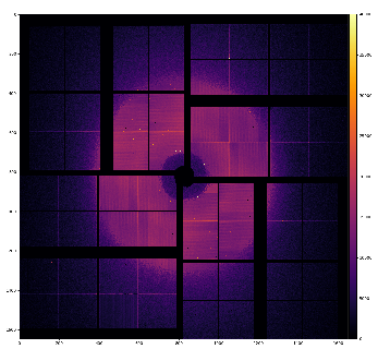
...
- nda = calib_epix10ka_any(det, evt)
- nda *= det.mask(par, calib=False, status=True, edges=True, central=True, width=1, wcentral=1, mode=0)
...

Manual alignment on 2019-05-06
...
Overview
Content Tools