Page History
...
- For CSPAD with moving quads (i.e. for CXI) optical measurement is done separately for each quad. The numeration of corners is shown in the plot:
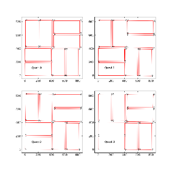
For each quad measurement is started from the point #1 which in assembled detector is closest to the beam. The 1-st point (x,y,z) coordinates are re-set to (0,0,0) in the beginning of measurements. At the end, it is checked that the 1-st point coordinates are reproduced within precision of measurement. - For CSPad CSPAD with fixed quad geometry (i.e. for XPP) optical measurement is done for entire detector. The 1st The numeration of corners in this case is shown in the plot:
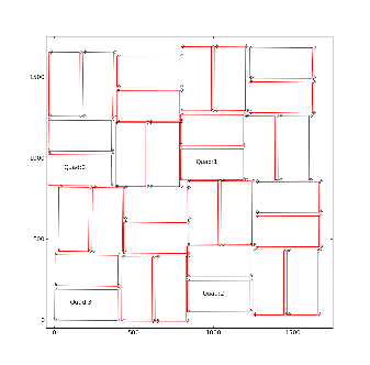
The 1-st corner of the 3-rd quad (x,y,z) coordinates are re-set to (0,0,0) in the beginning of measurements for . At the , as shown in the plot
end, it is checked that the 1-st point coordinates are reproduced within precision of measurement.
Corner coordinates are measured in micrometers (um (micrometers) and are saved in the xlsx format table, also containing numeration of quads and points. Then, xlsx format table is converted by hands to the text format in order to feed the python script for quality check and getting calibration parameters for 2x1 center coordinates and tilt angles.
...
This quality check works well to catch significant typos in input table. In case of obvious typos input table can be corrected. When the quality check is passed successfully the alignment parameters are saved in deployed under the calib directory as explained below.
Alignment parameters
The official place for CSPad alignment parameters is
/reg/d/psdm/<INSTRUMENT>/<experiment>/calib/CsPad::Calib<VERSION>/<CSPad-name>/<type>/<run-range>.data
The file name consists of the run range followed by the .data, for example, 0-end.data, 11-end.data, 47-52.data, etc.
All alignment parameters are splitted for 9 types:
center- x, y, z center position of each 2x1 for all quadrants. Comes from optical measurement.center_corr- additional manual correction to the center parameter. Can be applied if the optical measurement has (non-)obvious problems.marg_gap_shift- margins, gaps, and shifts between quads, as explained below. Comes from image-based tuning.offset- x, y, z coordinates for 4 quads. Fairly-reasonable assigned before tuning of theoffset_corrandmarg_gap_shiftparameters.offset_corr- additional correction to the offset. Comes from image-based tuning.quad_rotation- 4 quad rotation in n*90 degree. Comes from basic geometry.quad_tilt- 4 quad tilt in fractional degree. Has never been used. In latest optical measurement is accounted through the global 2x1 coordinate measurement in the detector.rotation- 8 2x1-rotation angle for 4 quads in n*90 degree. Comes from basic geometry.tilt- 8 2x1-tilt angle for 4 quads in fractional degree. Comes from optical measurement.
All coordinates are defined in size of pixel, which is 109.92 x 109.92um (and 274.80 x 109.92um for two rows between two of 2x1 ASICs.) The quadrant size is pre-defined as 850x850. The margines, shifts and gaps are defined for these quads. The offset and offset_corr are defined for low-left angle of the rotated by n*90 degree quad. Size of entire CSPad image does not matter for this alignment.
offset_corr
For individual quad position alignment use file: offset_corr/<run-range>.data
| Code Block |
|---|
dXq0 dXq1 dXq2 dXq3
dYq0 dYq1 dYq2 dYq3
dZq0 dZq1 dZq2 dZq3
|
marg_gap_shift
For common gap and shift between quads correction use file marg_gap_shift/<run-range>.data
| Code Block |
|---|
offset of 2x1s in quad (for tilt)
/ offset of quads in image (for tilt)
/ / gaps
/ / / shifts
/ / / /
X: 15 40 0 32
Y: 15 40 0 32
Z: 0 0 0 0
|
Overview
Content Tools