Content
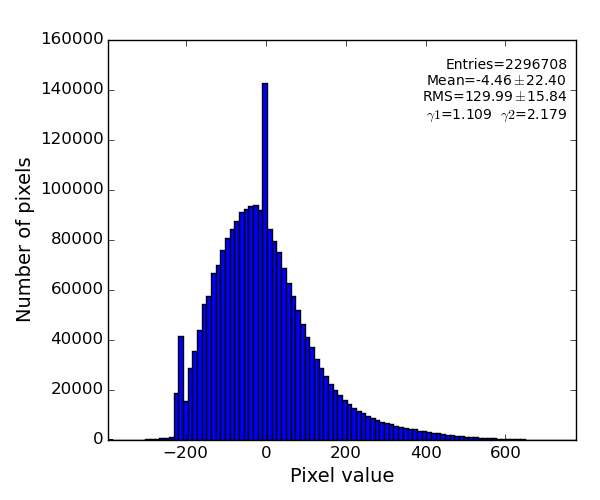
This algorithm is intended to subtract background from "non-assembled" images with approximately angular-symmetric radial distribution of intensities.
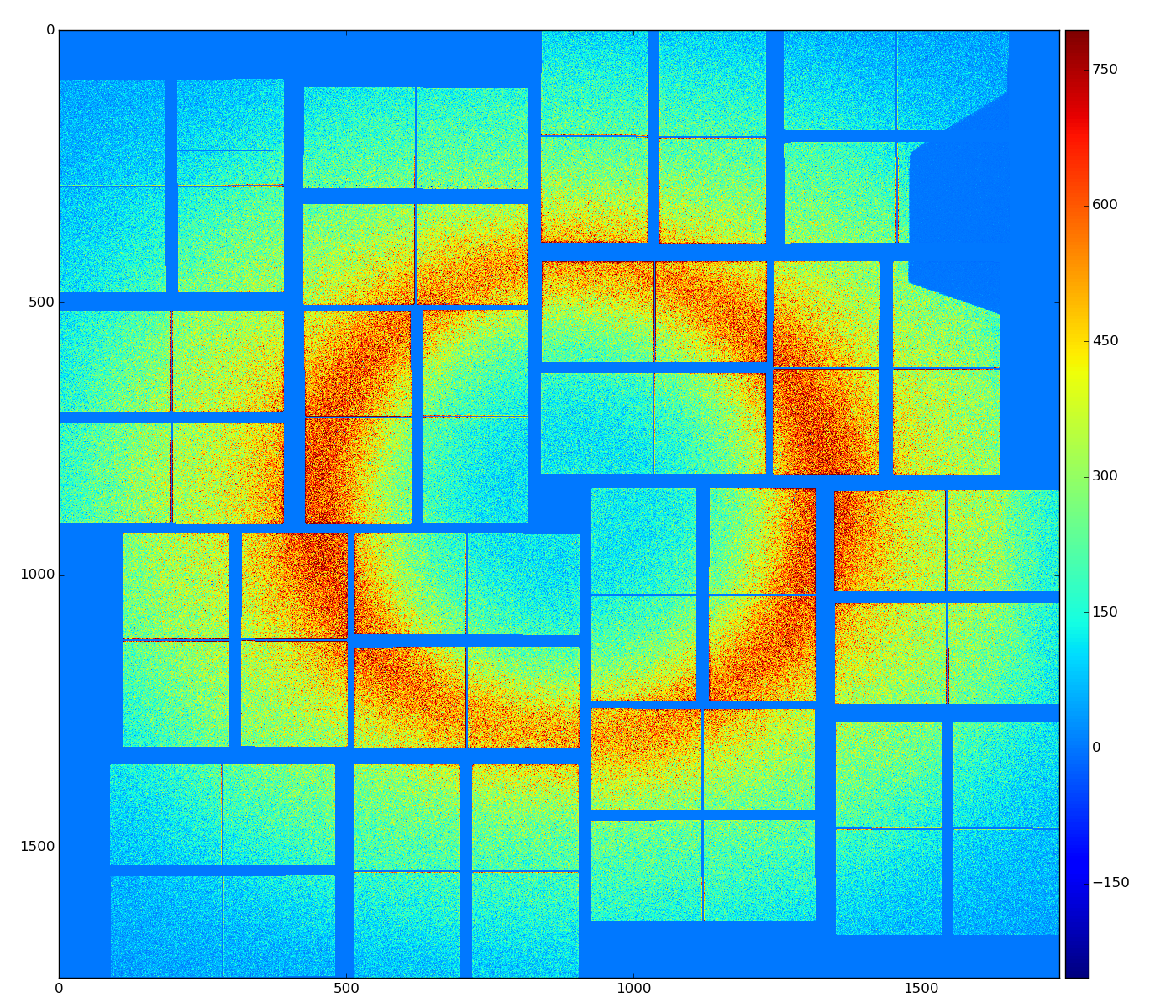
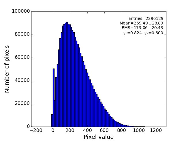
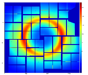
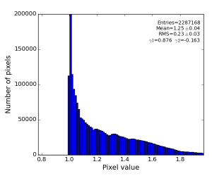
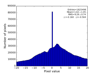
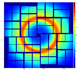
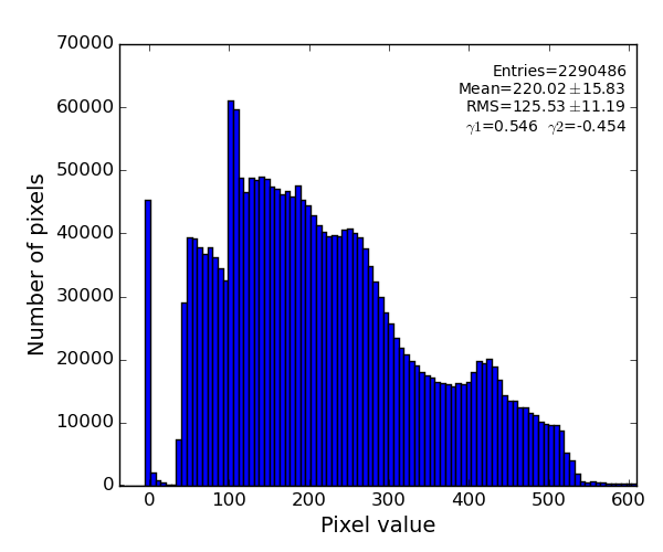
For example, pure water ring background from exp=cxij4716:run=22 for single event has an angular symmetry as shown in the plot:
Code location
Class RadialBkgd resides in the package pyimgalgos.
Auto-generated documentation for class RadialBkgd
Initialization
from pyimgalgos.RadialBkgd import RadialBkgd, polarization_factor
rb = RadialBkgd(xarr, yarr, mask=None, radedges=None, nradbins=100, phiedges=(0,360), nphibins=32)
See parameters' description in Auto-generated documentation for class RadialBkgd.
Input n-d arrays can be obtained through the Detector (AreaDetector) interface or directly through the class working with geometry. For example,
from PSCalib.GeometryAccess import GeometryAccess
geo = GeometryAccess(fname_geo)
xarr, yarr, zarr = geo.get_pixel_coords()
iX, iY = geo.get_pixel_coord_indexes()
mask = geo.get_pixel_mask(mbits=0377) # mask for 2x1 edges, two central columns, and unbound pixels with their neighbours
...
Algorithm
To evaluate background n-d array of data is split for 2-d bins in polar coordinate frame. Total intensity and number of involved pixels are counted for each bin and converted to the average bin intensity. Then this averaged intensity is per-pixel subtracted from data n-d array.
Input per-pixel coordinates passed as numpy n-d arrays xarr and yarr are used to evaluate per-pixel radial and polar angle coordinate arrays:
rad = rb.pixel_rad()
phi = rb.pixel_phi()
Binning parameters radedges, nradbins, phiedges, nphibins are used to initialize 2-d bins using class HBins. Initialization with default binning parameters covers entire detector coordinate space.
Non-default binning, for example like
rb = RadialBkgd(X, Y, mask, nradbins=3, nphibins=8, phiedges=(-20, 240), radedges=(10000,80000))
defines angular pixel coordinates with correct offset relative to minimal angle,
and gives 3 bins in radial direction from 10mm to 80mm and 8 bins in angle from -20 to 240 degree:
rad = rb.pixel_rad()
iseq = rb.pixel_iseq()
Pixels masked by the n-d array passed in the parameter mask are excluded from this algorithm and are not corrected.
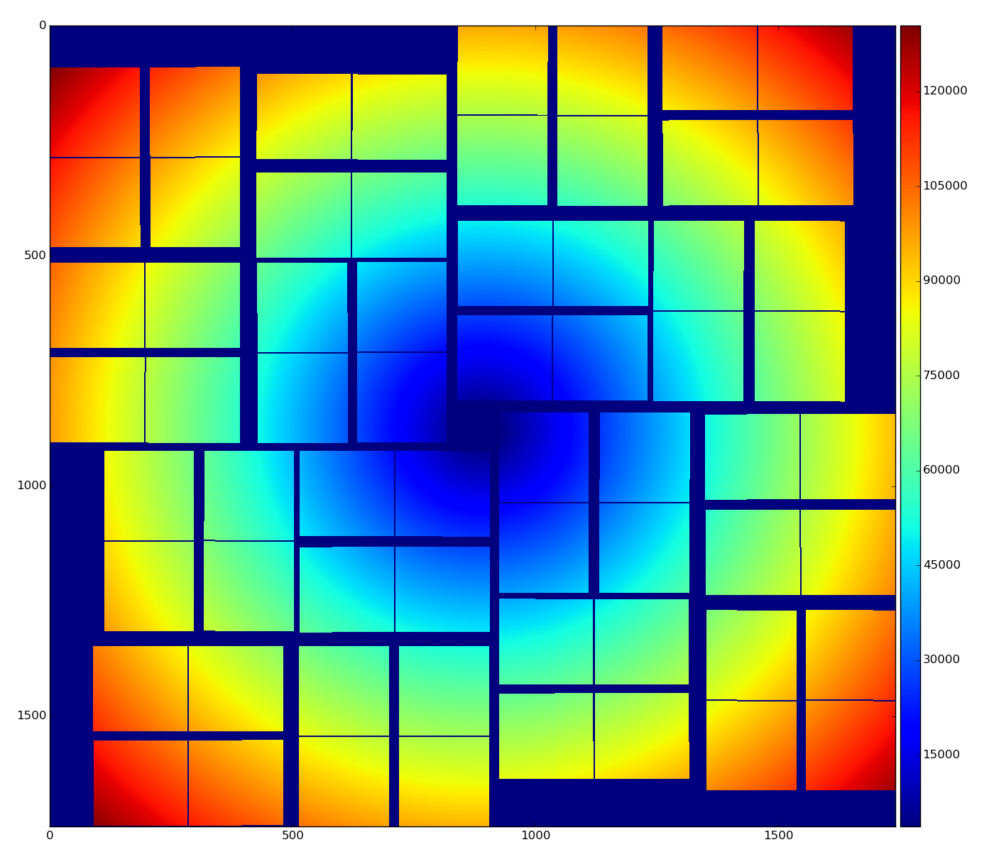
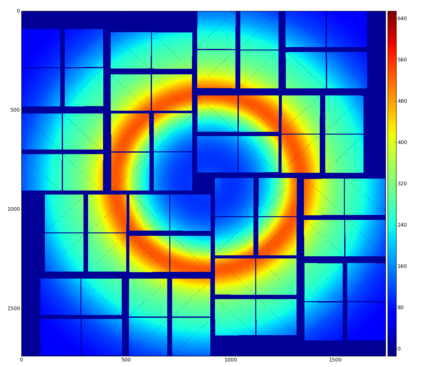
Averaged background intensity for default (nradbins=200, nphibins=32) and non-default (nphibins=8, nradbins=500) binning cases :
bkgd = rb.bkgd_nda(nda)
Background subtraction
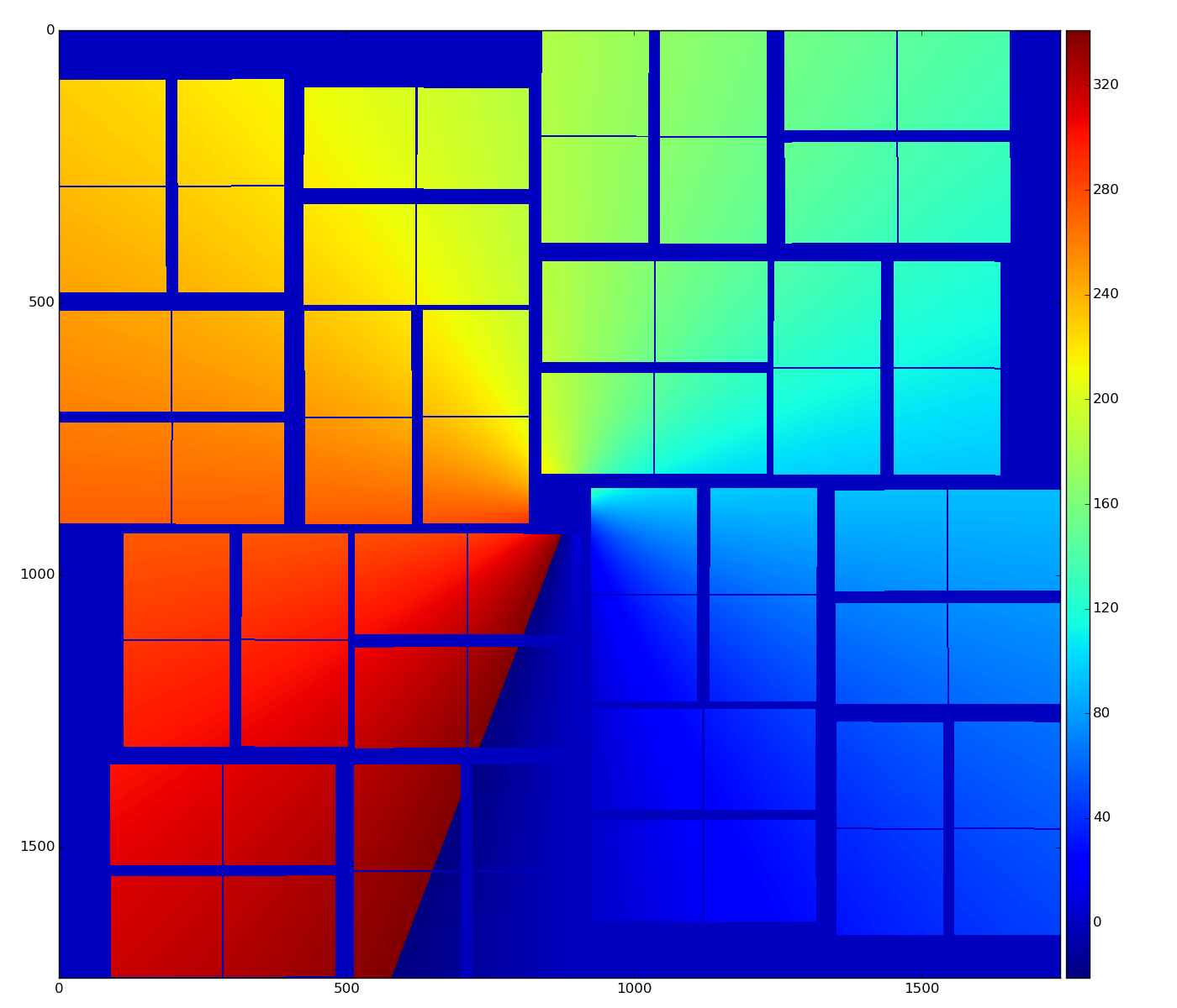
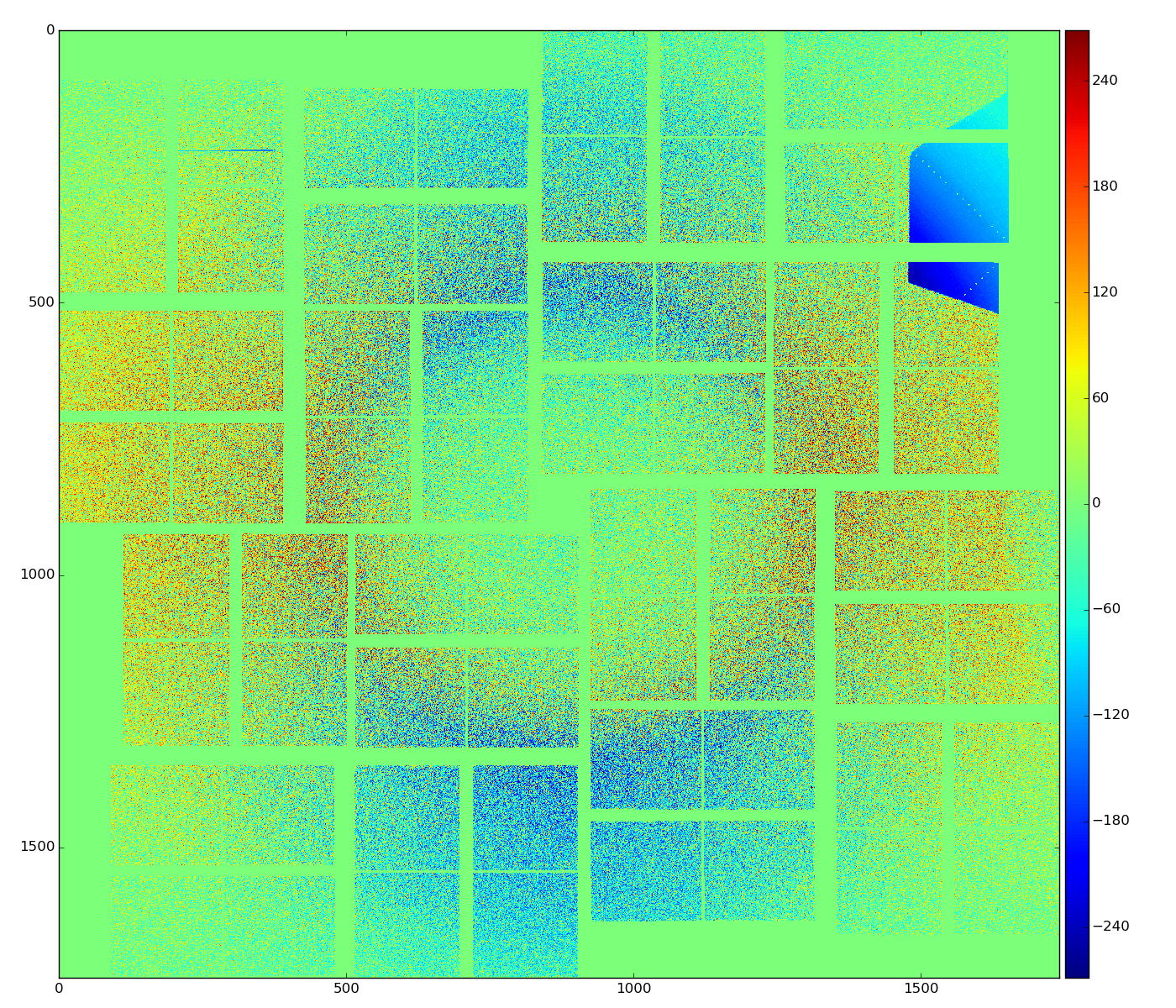
Background subtracted data for default (nradbins=200, nphibins=32) and non-default binning cases (nradbins=500, nphibins=1), and (nradbins=500, nphibins=8, phiedges=(-20, 240)):
res = rb.subtract_bkgd(nda)
Polarization correction
- For good statistical precision of the background averaging 2-d bins should contain large number of pixels. However large bins produces significant binning distortion which are seen in resulting image.
- The main reason for angular bins is a variation of intensity with angle due to polarization effect. The beam polarization effect can be eliminated with appropriate correction.
Method for polarization correction factor:
Then, radial background can be estimated using ring-shaped radial bins, single bin in angle:
arr = load_txt(fname_nda)
rb = RadialBkgd(X, Y, mask, nradbins=500, nphibins=1)
pf = polarization_factor(rb.pixel_rad(), rb.pixel_phi(), 94e3)
nda = rb.subtract_bkgd(arr * pf) * mask.flatten()
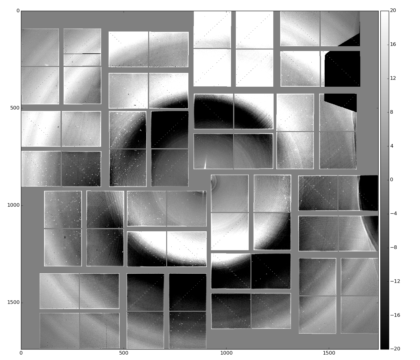
For exp=cxij4716:run=22 z=94mm
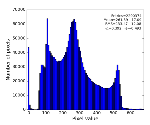
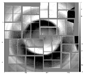
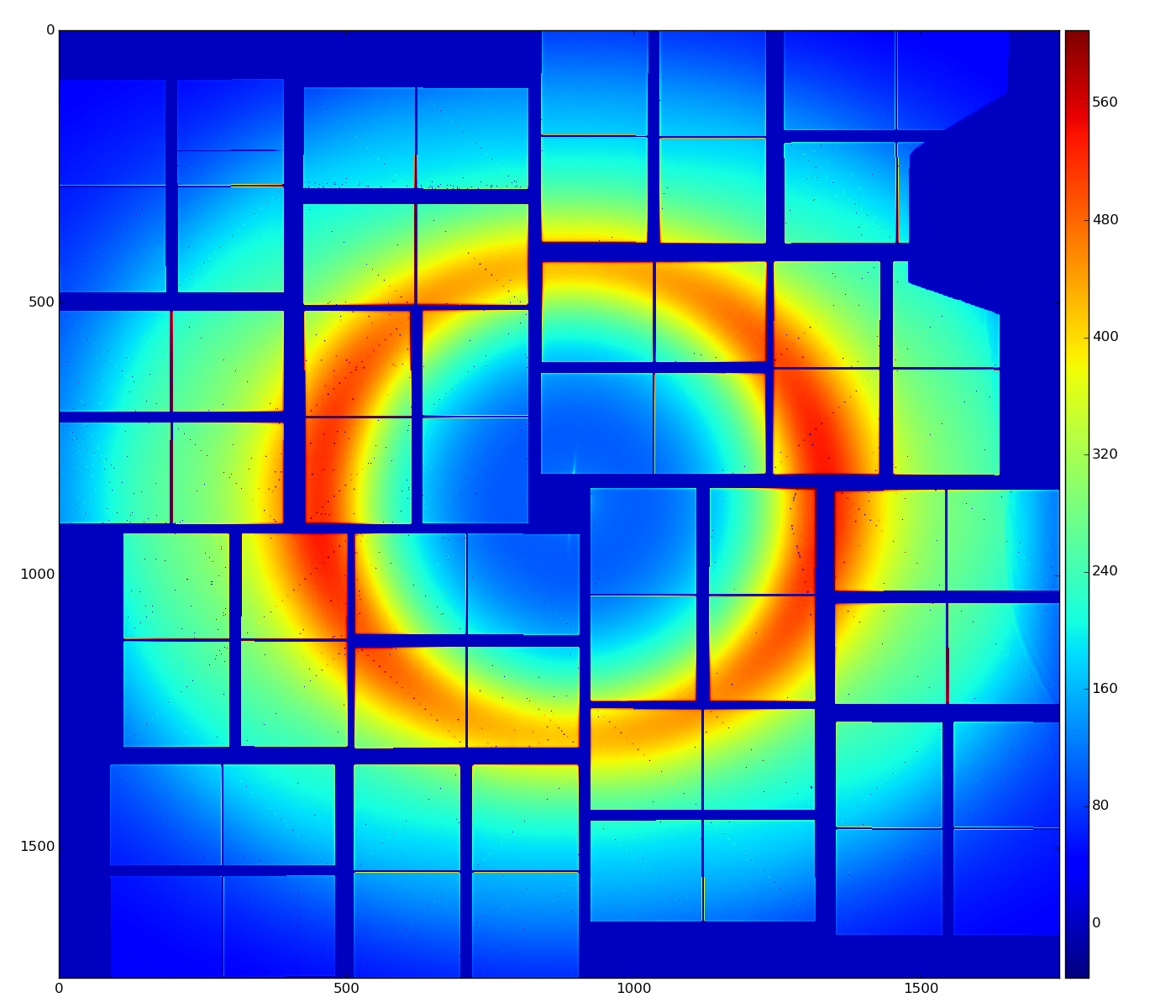
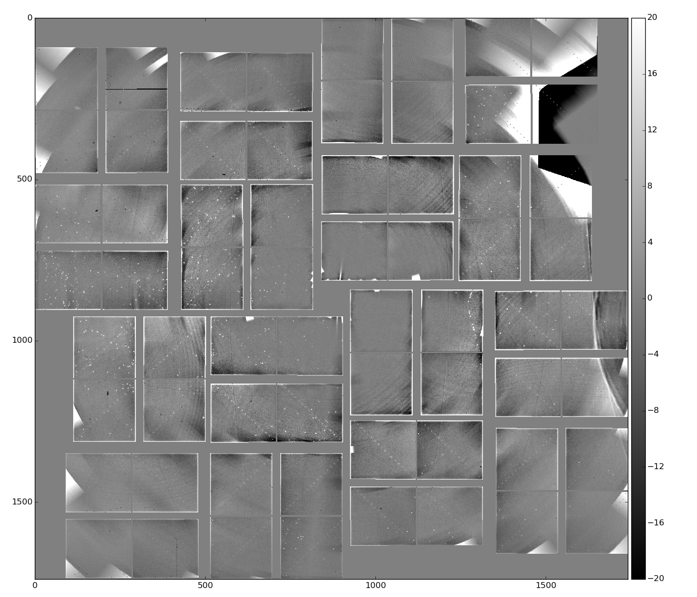
- averaged over all 14636 events calibrated (pedestal, common mode) data
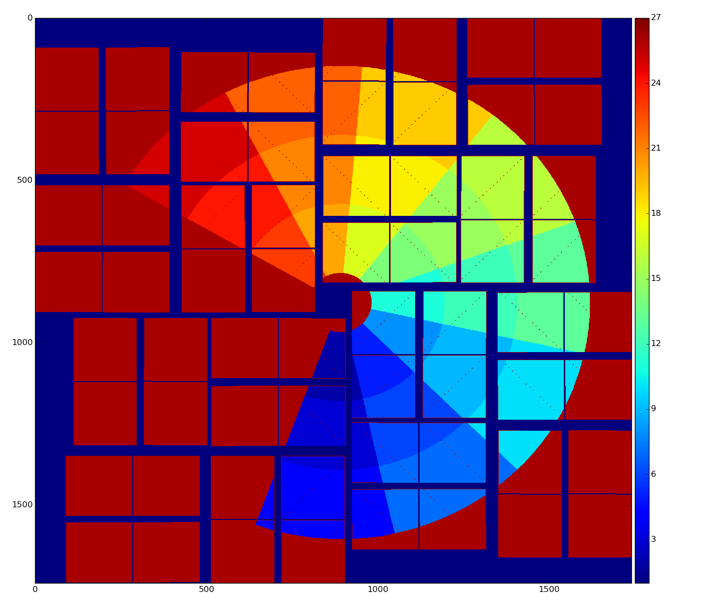
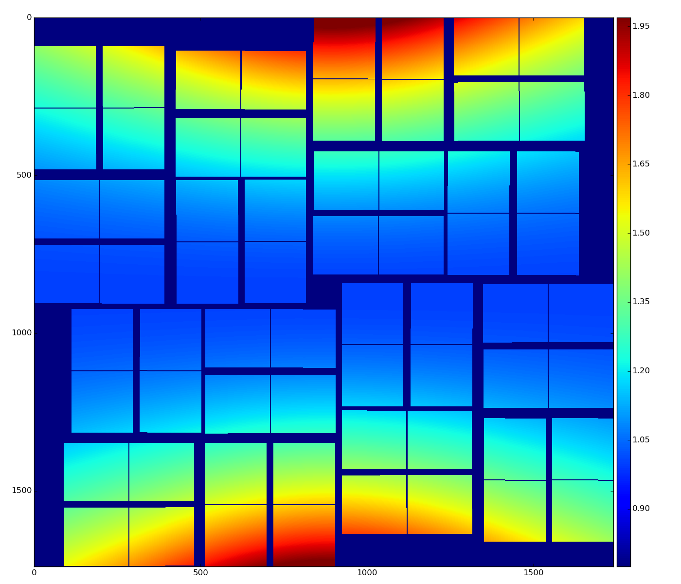
- polarization correction factor
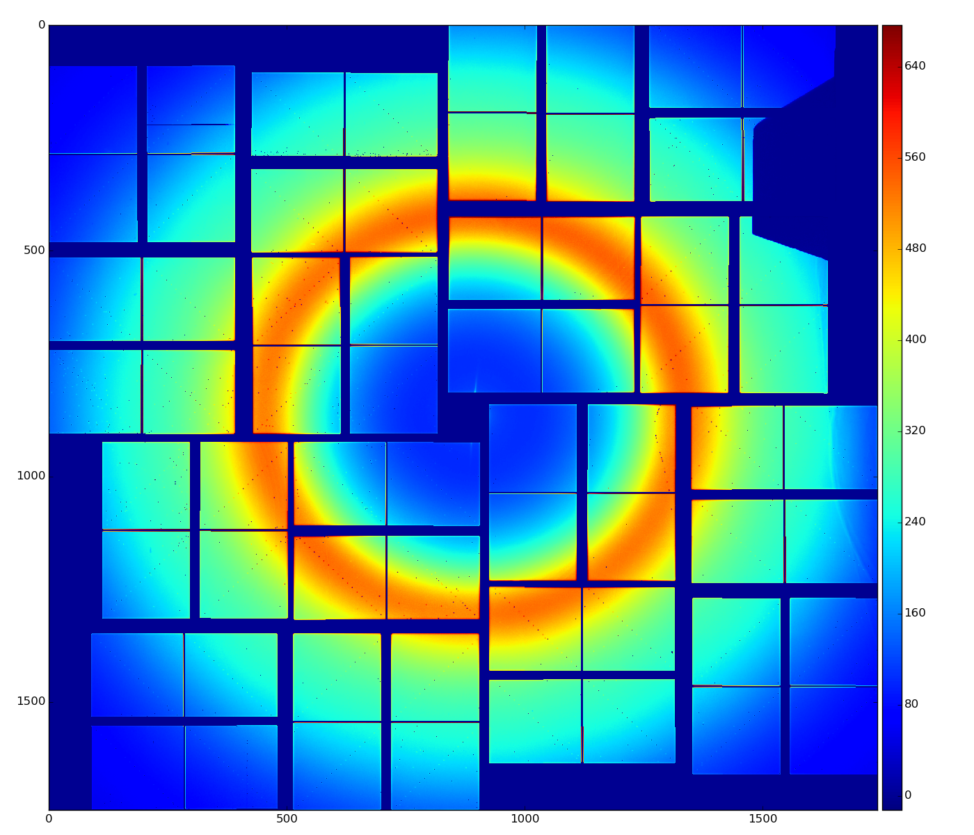
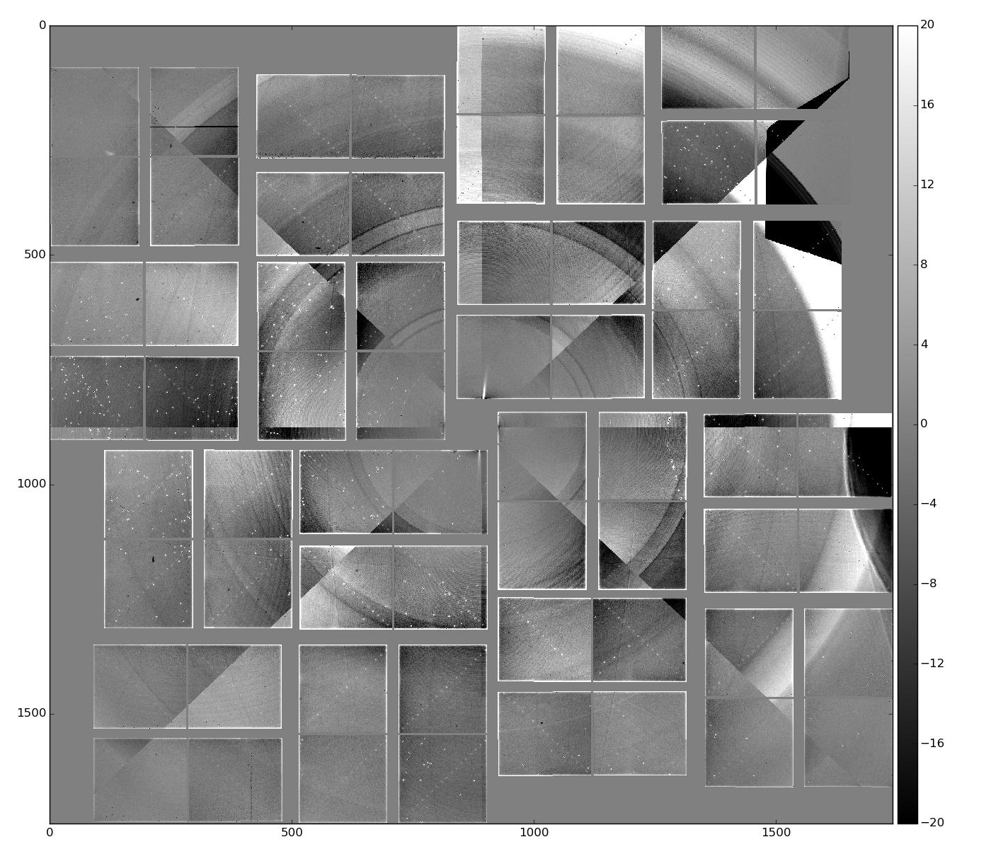
- polarization-corrected data
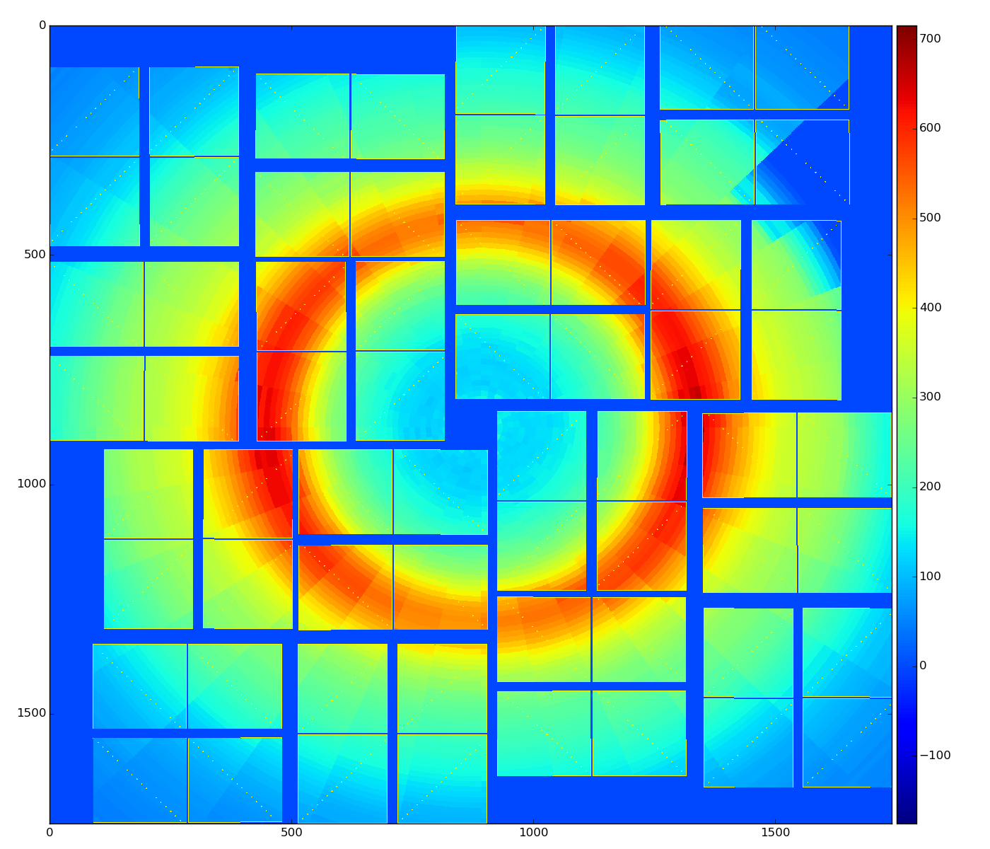
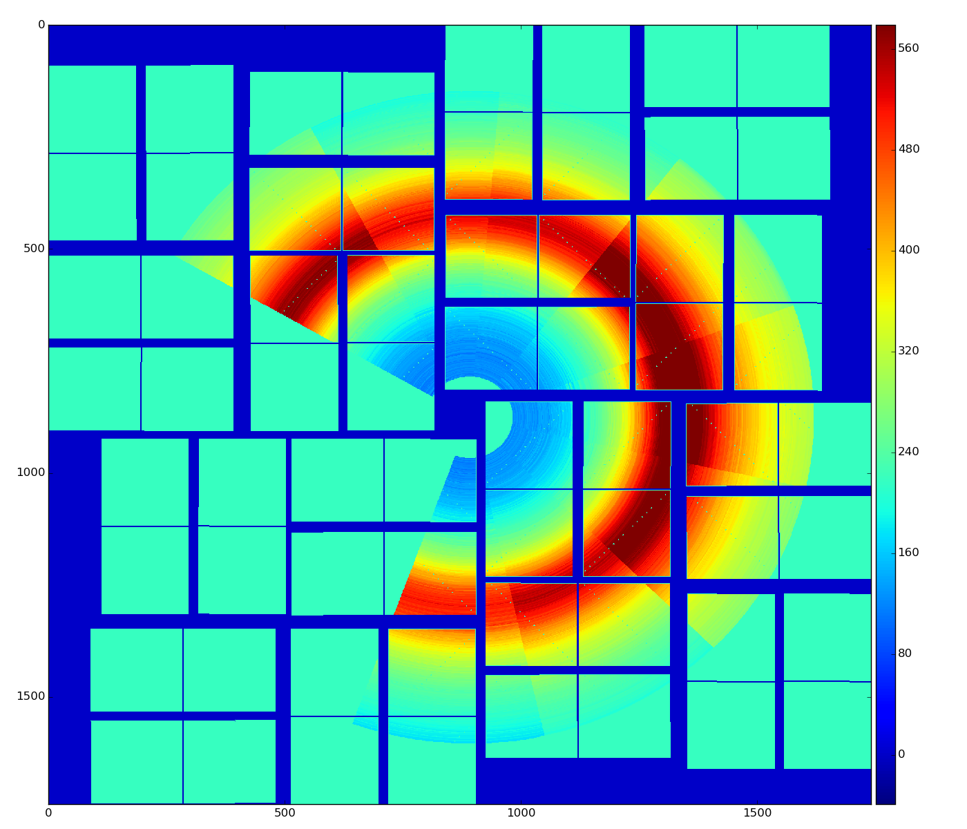
- radial-background subtracted data using single angular bin
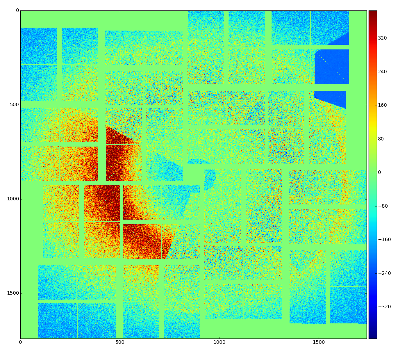
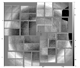
This image indicates on in-correct geometry; background center consistent with beam intersection does not coincide with detector origin (0,0). - radial-background subtracted data using 8 angular bins
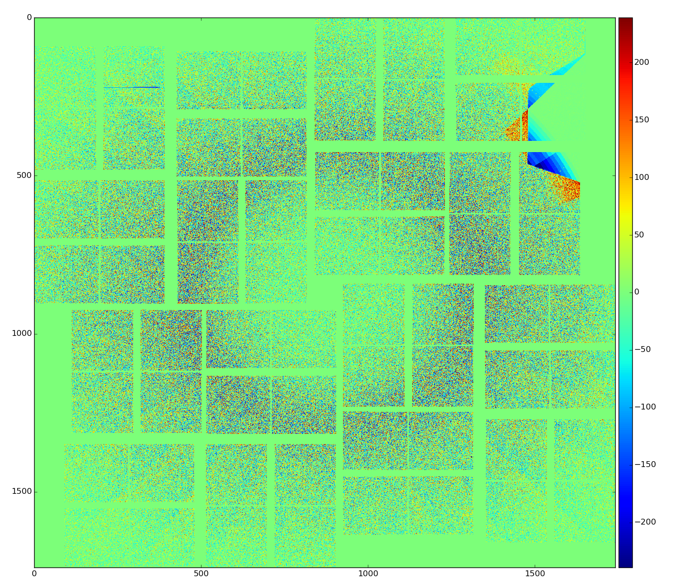
dynamically apply some geometry correction
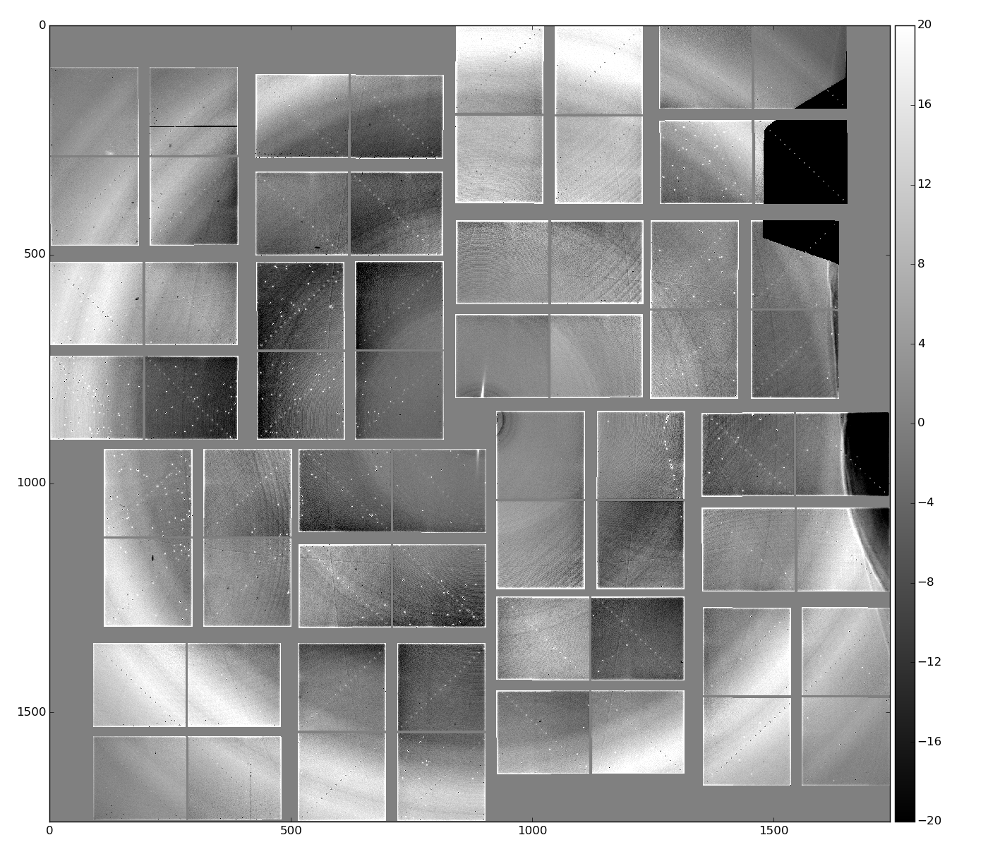
    geo = GeometryAccess(fname_geo)
    geo.move_geo('CSPAD:V1', 0, 1600, 0, 0)
    geo.move_geo('QUAD:V1', 2, -100, 0, 0)
and plot again radial-background subtracted data using single angular bin

we get that "dish"-like shape disappears.Interpolation (linear) between centers of the background bins could also help:
    bkgd  = rb.bkgd_nda_interpol(nda, method='linear') # method='nearest' 'cubic'
    cdata = rb.subtract_interpol(nda, method='linear')
Interpolation for entire detector and for part of the image:
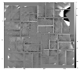

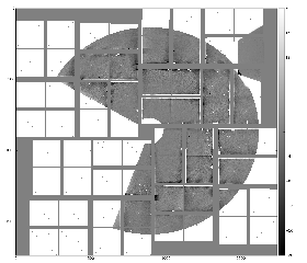
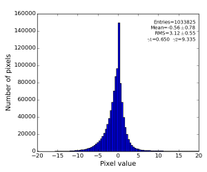
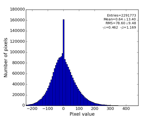
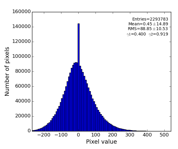
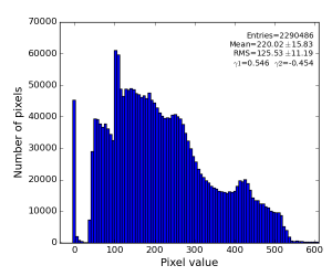
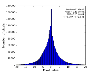
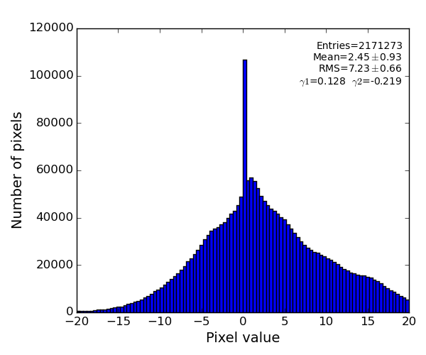
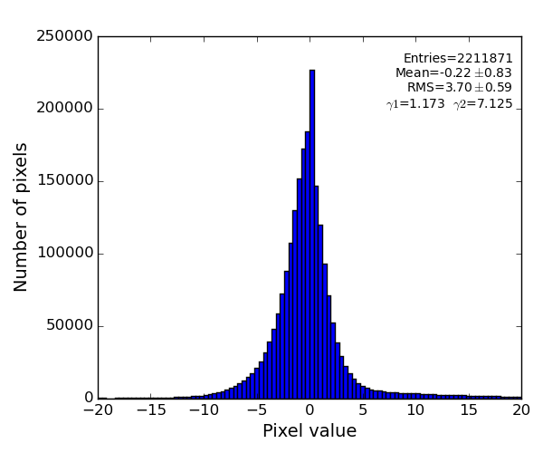
Image is not as impressive as for polarization-corrected sample, but the residual intensity spread shrink down to RMS~3 ADU.
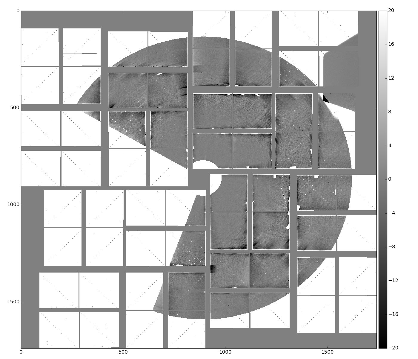
- Single angular bin interpolated background, and its subtraction from data:


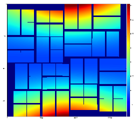
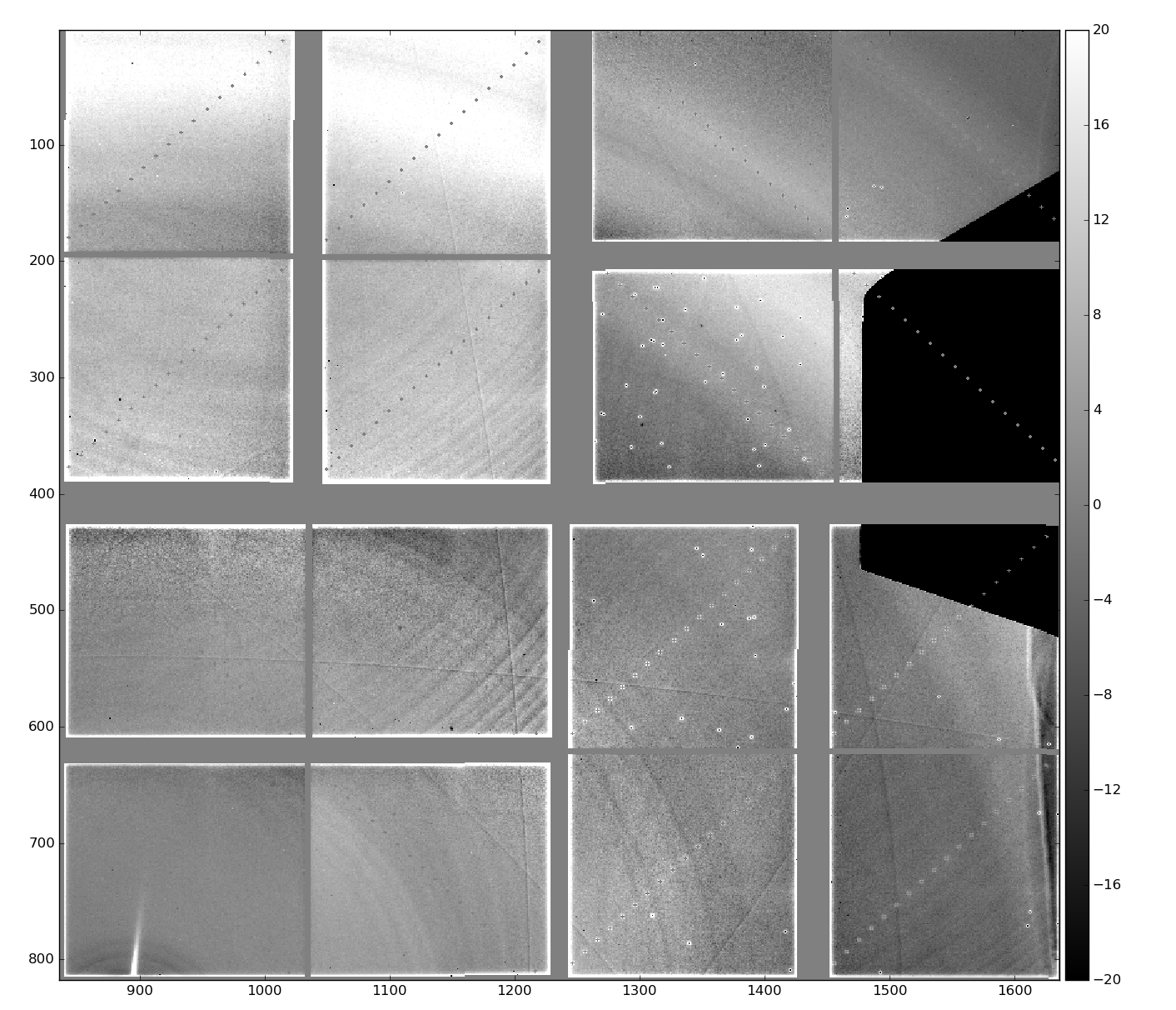
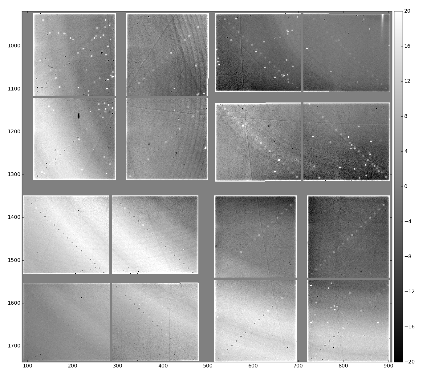
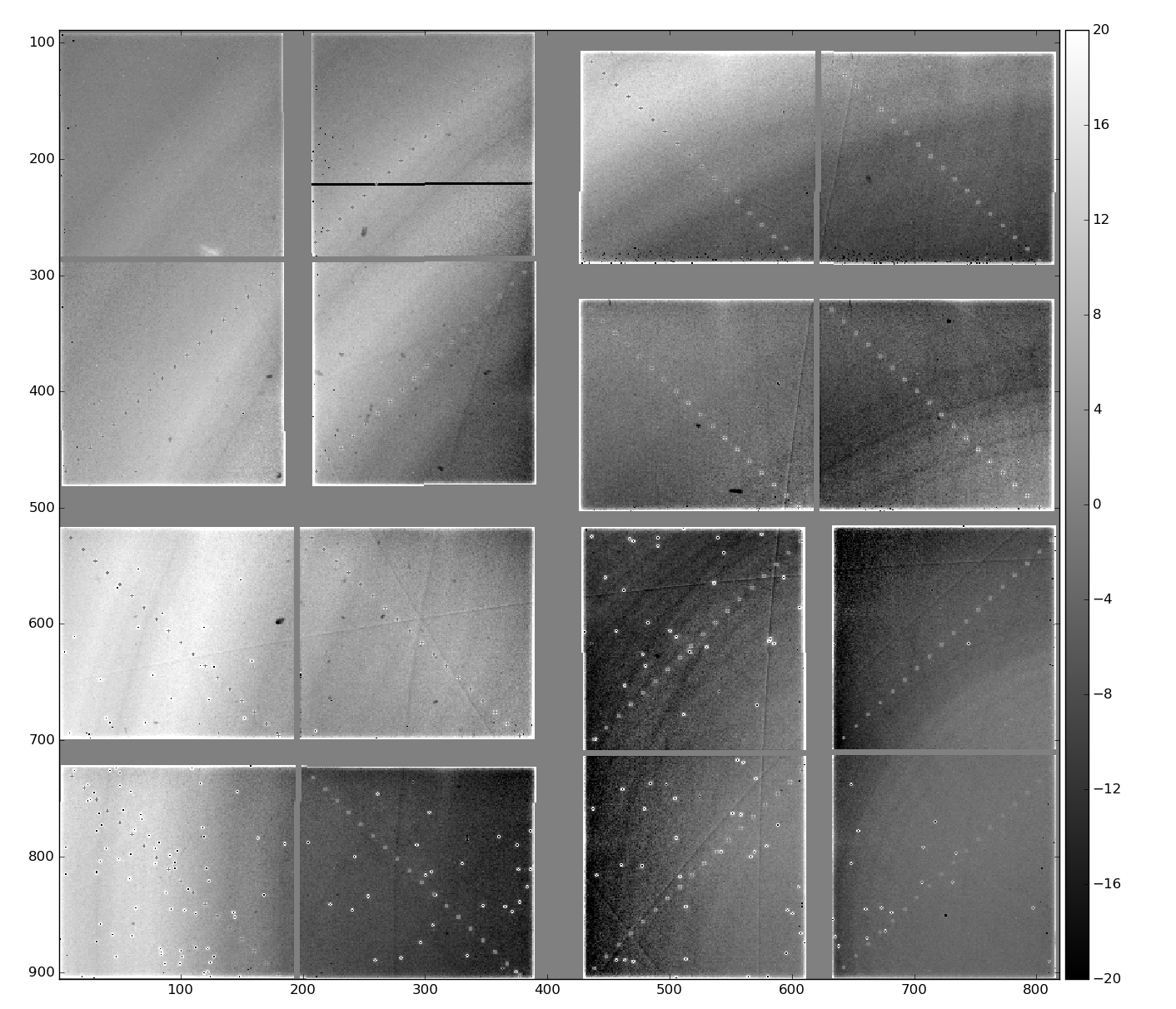
CSPAD "dopping" artifacts
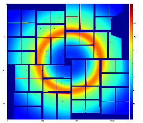
- zoomed-in regions of four quads
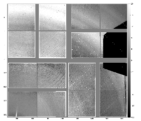
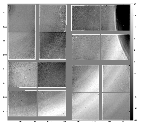
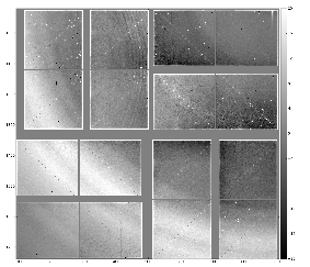
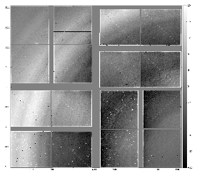
- Shows some "doping" artifacts.
- A few smooth curves earlier interpreted as "scratches" apparently become a nice "chart" probably on the detector shield. This "chart" can be used for alignment.

References
Overview
Content Tools