Introduction
The so-called "goose trigger" is a system where the laser is fed by two triggers that add up to a nominal trigger value (i.e. 9 Hz + 1 Hz = 10 Hz) but the laser to e-beam locking system is only fed by one of those triggers. This allows a user to have some laser pulses synchronized to the e-beam and some not synchronized, or even delayed, with respect to the e-beam. The idea is that you can remove backgrounds if you have laser on and off shots, where the off shots are delayed by ~14 ns so that the amplifiers stay warm.
Trigger System Block Diagram - Goose Trigger
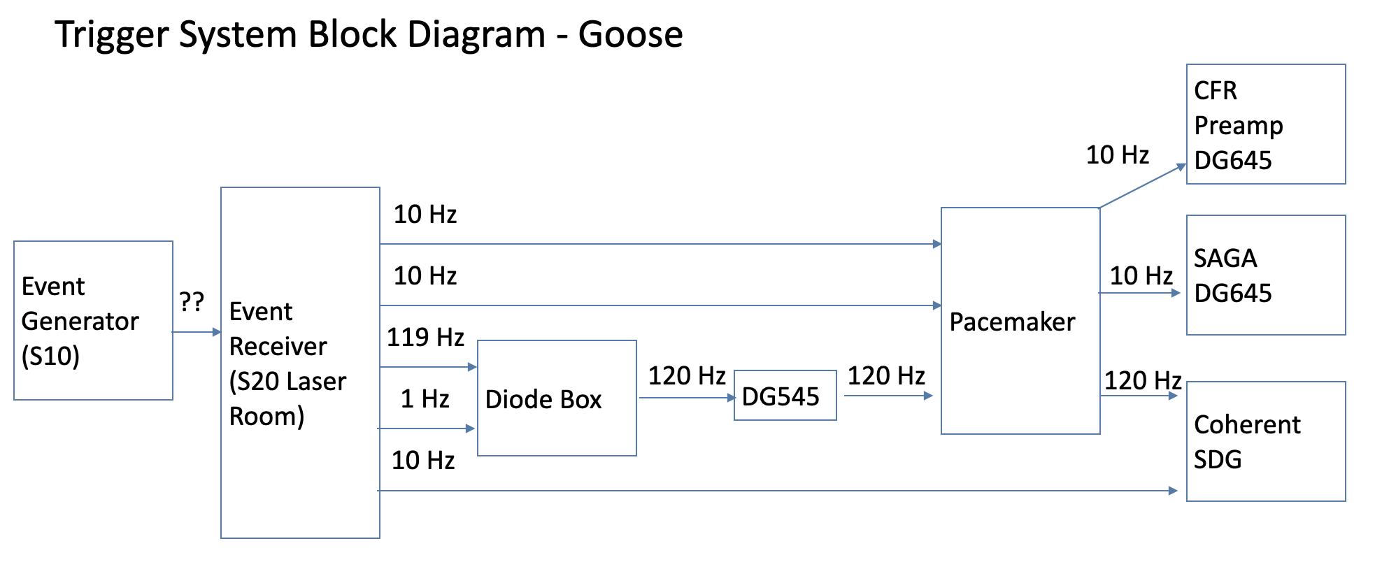
The "Diode Box" is what is used to combine triggers when in goose trigger mode. In this case the box is combining 119 Hz with 1 Hz to make 120 Hz to trigger the regen. The DG545 is used as an amplifier because the diode drop across the diode (about 0.6V) from the diode box makes the signal into the pacemaker too low. The DG545 is programmed to add a small delay to the 120 Hz signal for future flexibility, this box should never be adjusted. The pacemaker is a box that measures the frequency of the incoming signals and if they differ from the expected 10 Hz of 120 Hz (channel specific) by more than 1 Hz it provides its own 10 or 120 Hz. This is to ensure the laser always gets triggers. The DG645 and Coherent SDG convert the EVR triggers into various triggers for the lasers. These boxes are very rarely adjusted.
How does the goose trigger work?
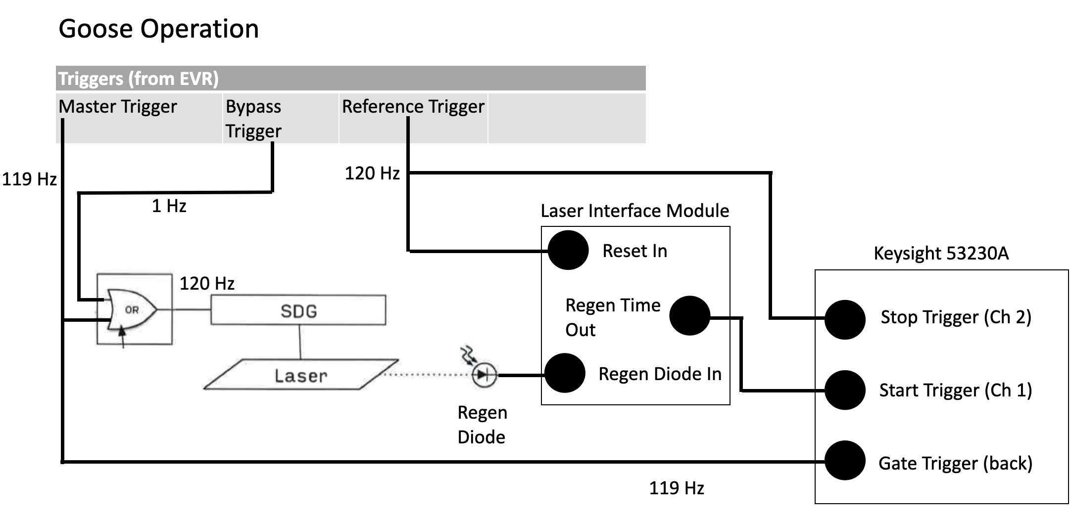
When using a "goose trigger", the laser (through the SDG) is fed a signal that is 120 Hz, but only a portion of that 120 Hz is used by the laser timing software. The "gate trigger" on the Keysight box tells the keysight box "start listening for a start and stop trigger". So in the diagram above the Keysight box is only updating at 119 Hz. The "bypass trigger" is a trigger that bypasses the laser timing system, so it can be changed to anything without disrupting the ability of the laser timing system to keep the laser and e-beam in sync.