Known differences between ACD model in GlastRelease and Reality
- Overlaps between top tiles go in the wrong direction
- Screws are not simulated
- Curvature of top tiles is not modeled. We have tentatively agreed with the ACD to simulate this through the introduction of a vertical box.
- Shingling along the sides is not included.
Testing the leakage of the ACD geometry as currently simulated in GlastRelease - Oct2005
Outcome of conference call between Bill Atwood, Heather Kelly, Alex Moiseev, and Steve Ritz on Oct 19, 2005
Before proceeding with large scale background rejection studies, Bill needs to be assured that the ACD geometry model as simulated in GlastRelease is worst case in terms of leakage. It is strongly believed that Alex's Geant3 simulation is more accurate. Interested in demonstrating that when the ACD model in GlastRelease is "improved" to adhere to the full design, that new sources of leakage will not be introduced.
The Plan
Provide a direct comparison between Alex's Geant3 simulation and what is currently in use in GlastRelease. If we can demonstrate that the GlastRelease model is the same or slightly worse than Alex's Geant3 simulation, Bill will be satisfied. We spent the rest of the call outlining the details of a run to be performed using both simulations. Alex will forward a final set of details via email.
Alex's Geant3 Simulations
About the illumination scheme:
Our simulations use simpler approach:
vertexes are uniformly distributed over the 40 m by 40m square with the center placed at 5cm above the center of the top ACD plane. Since this is a flat geometry, the angles are simulated as:
0 < cos^2 (Theta) < 1 - actually solid angle
0 < Phi < 2 pi
This is a difference between your and our approach - you use cos(theta) for spherical geometry, but I - cos^2(theta) for Cartesian geometry.
Of course the cost of our approach is that many events are discarded because the large area of vertexes is needed to provide correct illumination of the instrument. There is an approximation at the edges of simulated area - of course it is larger than maximum angles causing 3-in-a-row but still some (small) fraction of events which could cause (large off-angle) triggers are missed. I remember that I did the study what is the reasonable size of simulation area (currently 40m by 40m) and came to this size.
To get 200K triggers I need to run about 10^8 trials.
First Geant 3 Run
The first run produced 6 events of 205,000 went with zero signal in ACD detectors; 2 more have signals at 0.1 mip
Of that 6 events:
3 events sneak through the side corners - probably the most vulnerable ACD place; they created triggers starting in SSD planes 8, 11, and 13;
1 event went through the tile mounting hole on the top;
1 event - through gap between tiles on the top. This occurs at around tiles overlap where the ribbons are bent such a way to leave larger opening; ribbon does not follow exactly the tiles because ribbon has to be bent with min bending radius of 1cm. I would call it second vulnerable place because I see quite a bit of such events
1 event - at ribbon gap at the top corner. This was a place of our concern where we had to increase the gap between the ribbon and the tiles (at the top ACD corner) to reduce the force applied to the PMT-clear fiber cable optical connection due to thermal stress. The gap here reaches 8mm. This non-uniformity of ribbon gap was simulated because we concerned about this place. But this is the first time when I see the event sneaking through this gap.
I started another 100M run to get more statistics on sneaking events
Second Geant3 Run
A second run produced 205K trigger. 9 events leaked through the ACD:
6 - through the corner gaps
2 - through gap between tiles in the top, at the bending edge where ribbon has large gap (8mm)
1 - through tile gap on the top
GlastRelease Simulations
Utilized GlastRelease tag v7r2gr2 - includes an updated AcdDigi that ingests mean PEs per PMT as obtained from Alex Moiseev (GSFC) and xmlGeoDbs v1r25p3 which modified the shrinkage of the tiles along the sides to avoid creating excess gap between the ACD bottom and CAL.
The generic jobOptions files were modified as follows:
- Accept all events, whether or not they triggered - so TriggerAlg.mask = 0 AND OnboardFilter.mask = 0
- Shut off Gaussian noise in the PMTs
- Shut off edge effects in the tiles
The 5 million events were generated in task (thanks to Tom Glanzman for his help getting this task going!):
http://glast-ground.slac.stanford.edu/Pipeline/task.jsp;jsessionid=CDEE45A31830E4380C1D019E7A00CA7D?task=1456
The Results from GlastSim
Originally 3 runs failed due to NFS problems - they've since been re-run but I didn't included them ..I'd already started looking at the other 97 runs and was too lazy to toss them in. So in reality, this considers 4.85 million generated events which resulted in 1,213,381 3-in-a-row triggers
Out of those triggers 364 events showed no hits in the ACD - where hit was defined as 0.1 MIP.
These events were peeled from the MC, DIGI, and RECON TTrees and are available here:
ftp://ftp-glast.slac.stanford.edu/glast.u15/DataServer/1130309366381/
All the events were viewed in the event display to categorize them.
There are some classes of events that should be discarded:
95 completely missed the instrument, the trigger was the result of noise
51 were CAL events that had backsplash which triggered the TKR and just didn't happen to hit a tile
2 hit the space-craft and interacted causing backsplash.
So that leaves us with 216 to consider.
Of these 134 truly missed any active material in the ACD.
64 of the remaining events did have at least one MC "hit" within a tile, but the tile was determined to be below threshold by the digitization algorithm.
18 had MC "hits" in ribbons that were determined to be below threshold in the digitization algorithm (though we should note that the algorithm for the ribbons needs adjustment - namely in terms of the mean number of PEs by position along the ribbon)
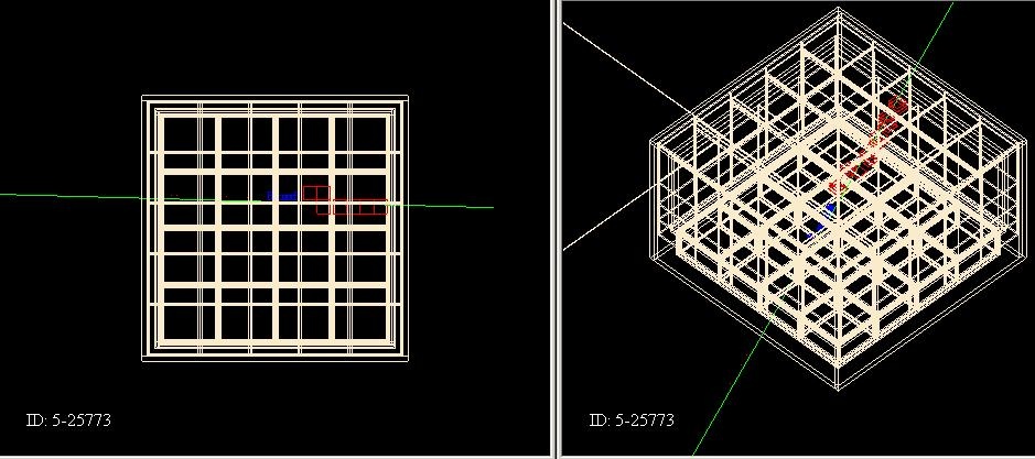
Of the 134 that failed to go through any active material in the ACD:
118 slipped through the gaps along the corners where the side tiles meet.
and
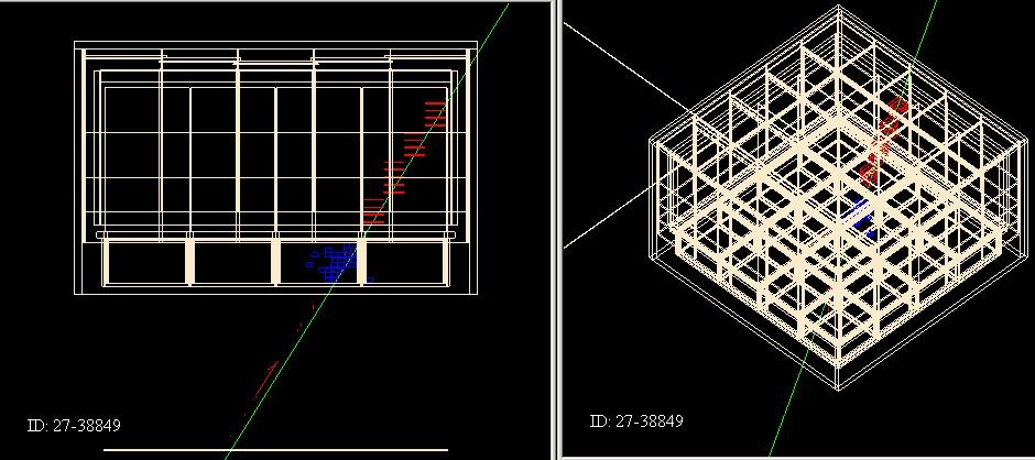
16 went through between two columns of side tiles on the same face, but didn't' seem to go through a ribbon.
Conclusions
The current geometry model in Gleam is more leak prone than the Geant3 model. The leakage through the side corner gaps is about 3-4 times larger than what is seen in the Geant3 model. Alex suggests that we look at how large those gaps are and check the distance between the ACD side tiles and the sensitive area of the TKR (current the G3 simulation is 8.5 cm).
Since the ACD in Gleam can be considered worst case, updating the ACD geometry will wait until after DC2.