Introduction
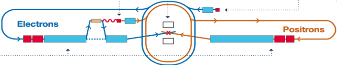
The International Linear Collider (ILC) is a newly-proposed electron-positron collider which will help physicists to answer compelling questions such as dark matter and the existence of extra dimensions. In its Reference Design Report (RDR), the two ILC Main Linacs, one for accelerating electrons and the other positrons, have a total length of 31 km long. The following is a schematic of the ILC.
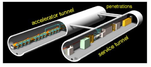
Each Main Linac will have a dual-tunnel configuration, one for acceleration and the other for service. In the acceleration tunnel, there will be about 20,000 superconducting cavities chained together to provide the acceleration of electrons or positrons to 500 GeV. The following is a schematic picture of the dual-tunnel configuration.
The Main Linacs account for about 30% (12% for RF and 18% for structures) of the total cost of ILC, which is estimated at 6.75 billion dollars at this moment. Therefore, any improvement in the design of the Main Linacs could lead to significant cost saving.
Simulation of the TDR Cavity
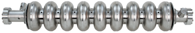
The baseline TDR cavity consisting of 9 cells and power and HOM couplers is shown below.
Using the complex eigensolver in Omega3P, the first-ever direct calculations of the dipole mode spectrum and the mode damping characteristics were obtained in 2005 on NERSC Seaborg supercomputer. The following shows the external Q's for 1st and 2nd dipole band modes from both Omega3P computations and the measured values of TTF module 3 from DESY databank. 531K high-order tetrahedral elements with 2nd order basis functions were used in the simulation, resulted to about 3.5 million DOFs. it took about 2 hours with 512 CPUs and aggregated 300GB memory to get the results.
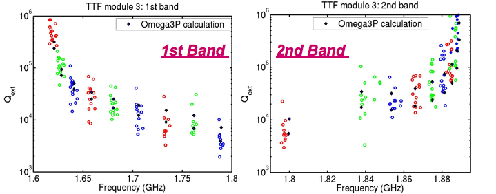
The above picture shows that the measured external Q's are scattered round the computed ones. This is due to the deformation of the cavities. We have developed a method to compute the deformation from the measurement data, through an inverse problem approach.
A new phenomenon of mode rotation was discovered using the visualization tool V3D for those dipole pairs where the spreads of a pair due to fintie Qs are comparable to the mode spacing of the pair. A pair without mode rotation is shown here, and that with rotation here.
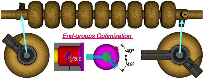
Endgroup Optimization for Low-Loss Desgin
The Low-Loss (LL) design for ILC accelerating cavities has 20% less cryogenic loss and higher shunt impedance than the baseline TDR cavity. However, the direct use of TDR High-Order-Mode (HOM) couplers provides inadequate HOM damping. Several dangreous modes were found in the 3rd dipole band from high-resolution simulation using Omega3P. The following is a picture of the Low-Loss cavity model and its end-groups.
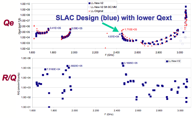
We optimized the end-groups using Omega3P and provided an improved design. The following is the comparison of Q and R/Q for the original design and the improved SLAC design.
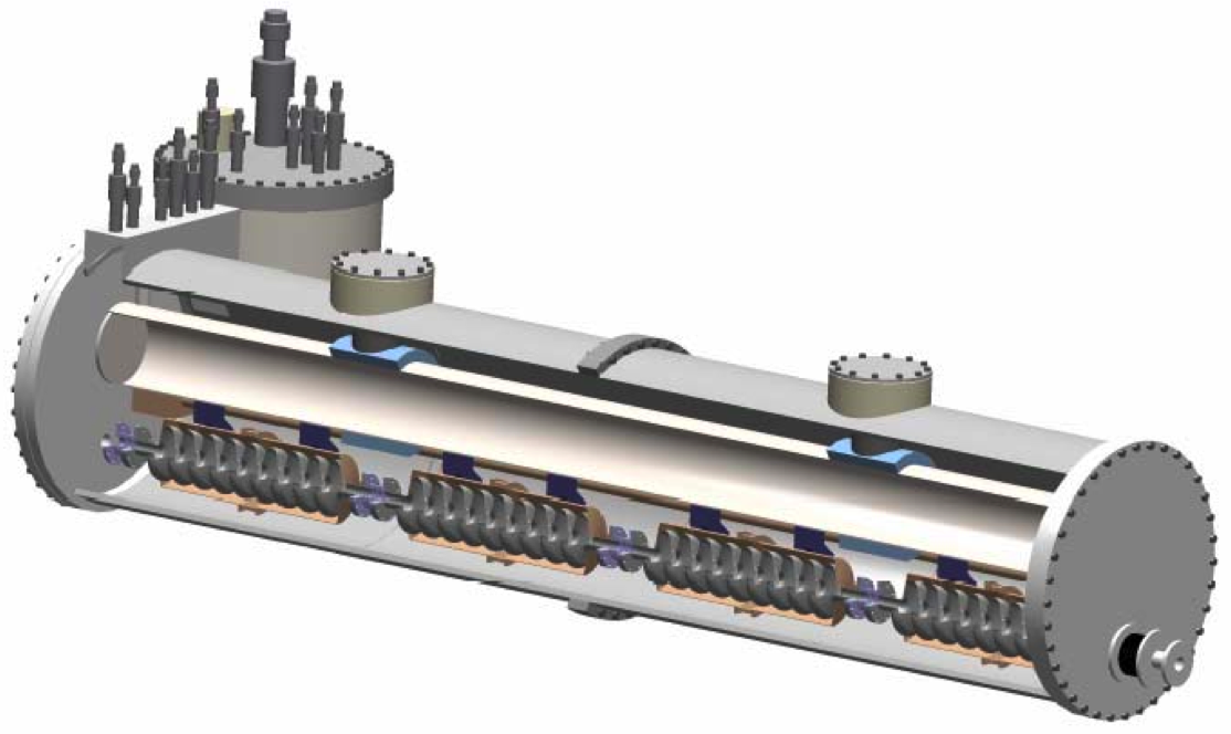
Modeling ILC STF 4-Cavity Super-structure
The Superconducting Testing Facility (STF) is a project at KEK, Japan to build and operate a test linac with high-gradient superconducting cavities KEK STF website. Its phase I will have a 4-cavity chained superstructure shown in the following,
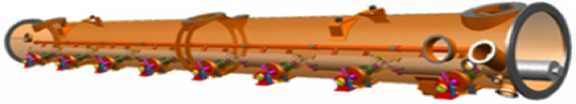
The STF 4-cavity superstructure was simulated at NCCS through an INCTIE/LCF award. The following shows the electromagnetic field distribution of a trapped dipole mode in the STF superstructure.

Click here to see an animated gif picture which shows the field distribution of the trapped mode as one traverses along the structure.
Modeling ILC 8-Cavity Cryomodule
The baseline design for the ILC cryomodule consists of 8 TDR superconducting RF cavities, and is shown in the following.
With the advances in solvers and numerical algorithms, we were able to simulate the ILC 8-cavity cryomodule with both trapped mode analysis using Omega3P and initial wakefield analysis using T3P. The following is a dipole mode pattern in the 3rd dipole band.

The following is the picture of the model we used in EM analysis.

Because of the large aspect ratio, it has become very challenging to visualize the modes in the cryomodule. Collaborating with the SciDAC Visualization researchers, we are addressing this issue.
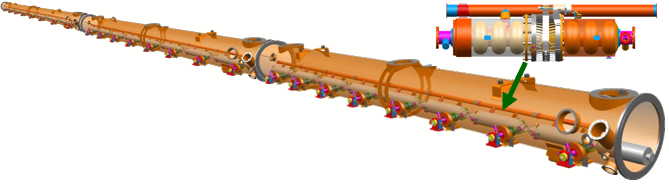
Modeling RF Unit of ILC Main Linac
A Grand Challenge problem for ILC simulations is to calculate wakefield effects in the 3-cryomodule RF Unit of ILC Main Linac assuming realistic dimensions and misalignments. The following illustrates an RF unit of the ILC Main Linac.
The computational analysis will include:
- trapped mode analysis and damping evaluation
- cavity imperfection effects on HOM damping
- wakefield effects on beam dynamics
- effective design of beam line absorber
Closely working with scientists in SciDAC CETs/Institutes, we are actively working towards solving the Computational Grand Challenge.