| Section | ||||||||||
|---|---|---|---|---|---|---|---|---|---|---|
|
This page is meant to be a working place for SLAC Pixel activities. General documentation about Pixel detector will also be found here.
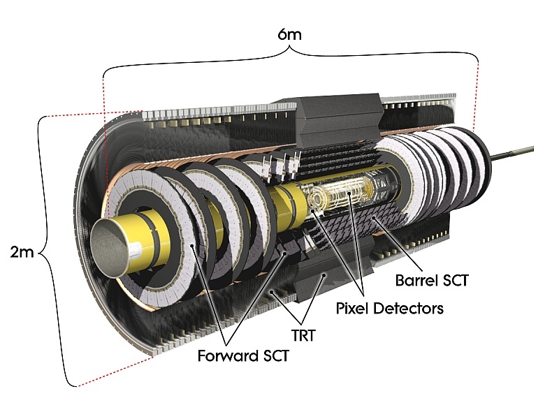
A Pixel sensor is a 16.4 x 60.8 mm wafer of silicon with 46,080 pixels, 50 x 400 microns each. A Pixel module comprises an un-packaged flip-chip assembly of 16 front-end chips bump bonded to a sensor substrate. There are 1744 modules in the Pixel Detector for nearly 80 million channels in a cylinder 1.4m long, 0.5m in diameter centered on the interaction point. The barrel part of the pixel detector consists of the 3 cylindrical layers with the radial positions of 50.5 mm, 88.5 mm and 122.5 mm respectively. These three barrel layers are made of identical staves inclined with azimuthal angle of 20 degrees. There are 22, 38 and 52 staves in each of these layers respectively. Each stave is composed of 13 pixel modules. In the module there are 16 front-end (FE) chips and one Module Control Chip (MCC). One FE chip contains 160 raws and 18 columns of pixel cells, i.e. 2889 pixels per FE chip or 46080 pixels per module. There are three disks on each side of the forward regions. One disk is made of 8 sectors, with 6 modules in each sector. Disk modules are identical to the barrel modules, except the connecting cables. The front-end chips are a major heat source (0.8W/cm2) dissipating more than 15kW into the detector volume. This heat is taken out via integrated cooling channels in the detector support elements: Staves in the barrel region and Sectors in the forward region. The pixel detector is shown in the image below, in the context of the entire ATLAS inner detector. It is the closest subdetector to the interaction region and has specific requirements to function within this high radiation enviroment.
The inner detector is composer of three separate sub-systems: Pixel, SCT and TRT.
This image shows a cross-section view of the pixel detector only. One can see the three barrel layers, and the three disks
The SLAC ATLAS group has a number of areas of involvement in the pixel system. Our group has involvement in the core DSP software, AnalysisFramework infrastructure, online data access via web browser, alignment and validation, and timing. We provide links to pages summarizing this work below. The groups work related to the inner detector upgrade can be found elsewhere in these pages: https://confluence.slac.stanford.edu/display/Atlas/Upgrade
