...
In the case of a chiller failure we saw the RTDs interlocks in Disabled state. They were re-enabled when the RTD readings were back in the interlock safe range.
...
Restoring the SVT temperature after a SVT Chiller failure
After an SVT Chiller failure the Power Supplies for HV will interlock. To check the status of the SVT LV/HV Power supplies go to
An example of the temperature ramp-down procedure can be found on :
https://logbooks.jlab.org/entry/3916838
| Note |
|---|
Do not go directly to -18C. It is recommended to bring the detector to the setpoint temperature step by step. |
- Prepare a myaPlot of the following quantities (from hps_epics click on the ! next to StripCharts and select myaPlot
- HPS_SVT:PLC:i:RTD_SVT_Return-Value ===> This is the return temperature from the SVT measured by an RTD (During a run is usually 4C higher than the Supply. 2C higher if not running)
- HPS_SVT:PLC:i:RTD_SVT_Supply-Value ===> This is the supply temperature read from the RTD. Usually 2C higher than the Chiller temperature
- HPS_SVT:CHILLER:TEMP:RD_ ===> The chiller temperature setpoint
- The SVT temperature at the restart of the chilling procedure will be unknown. One can try to find a good starting point by setting a temperature of the Chiller such that the Supply-Value is about 1 - 2 C below the Return Value and one can see the Return-Value decreasing. If the Return-Value RTD is increasing, it means that the Chiller setpoint temperature needs to be lowered. (see figure below at around 2:10 AM we were trying to find the proper setpoint temperature (green) and trying to put the Supply (blue) below the Return (gold)
- Gradually bring the setpoint temperature down trying to maintain about ~2C spread (ideally) between the Return and the Supply. In the figure below a spread of about 4C was used. One can notice that the supply temperature flattens faster at fixed setpoint but keeps bringing the return down. Try to go down in temperature to more or less maintain the temperature gradient more or less constant to optimise time
- At the end of the procedure, wait a bit to have the SVT at around -13.8C – -14C.
- At that point the Various interlocks can be restored
In this figure is shown the ramp down of the SVT Temperature as described in the procedure above.
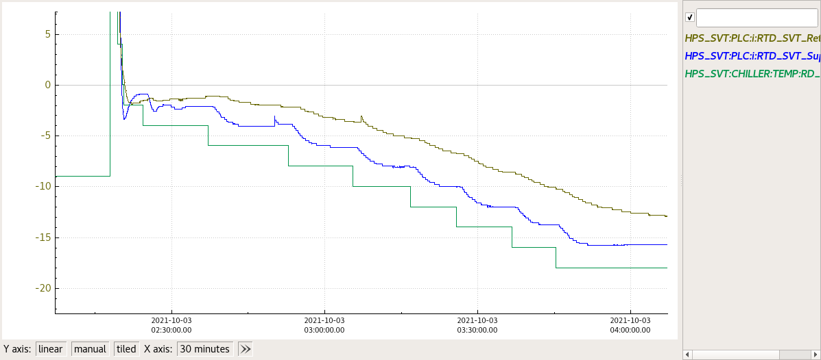 Image Added
Resetting MPOD Interlocks after SVT Chiller failure
After an SVT Chiller failure the Power Supplies for HV will interlock. To check the status of the SVT LV/HV Power supplies go to
http://hpsmpod/ (Accessible behind the hall-b firewall)
If you see "Interlock" in the last column, means that the Power Supplies are interlocked and need to be reset. It can be done on the expert hps_epics adl of SVT Bias.
On top of the page there is "Reset MPOD interlocks" in red. Click on it and then check if the interlocks are cleared on the the hpsmod webpagehttp://hpsmpod/