Search/Navigation:
Related:
SLAC![]() /EPP
/EPP![]() /HPS Public
/HPS Public![]()
Jefferson Lab![]() /Hall B
/Hall B![]() /HPS Run Wiki
/HPS Run Wiki![]()
S30XL-LESA/LDMX
Bottom COB has dtm1, data dpm going from dpm0 to dpm6 and control dpm is dpm7. It is marked as "0" with a marker, but can also be seen from the ID tag ending in 0 on the front of the COB.
Top COB had dtm2, data dpm going from dpm8 to dpm14 and control dpm is dpm15. It is marked as "1" with a marker, but can also be identified from the ID barcod tag ending in 1 on the front of the COB.
The RTM C03-01 and C03-02 were placed in the bottom and top location, respectively.
...
Use connectors with yellow strip (they seem to work best). Slow control channels have been tested to be working if placed in this configuration
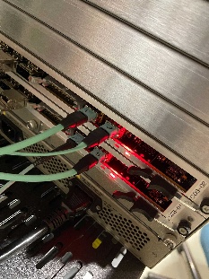
Image of connections on the RTM data side. The non-marked fiber is the type-B fiber which comes out from the breakout box. 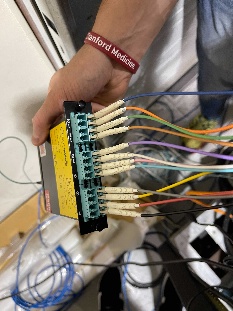
We decided to avoid connections on the DPM6 as this particular RCE showed few errors during testing.
To do so we used a breakout box to re-map the data connections.
For the HALL-B set-up:
1) Take breakout box labelled as "DATA"
2) Connect fiber type B in MTP1
3) Connect the octopus cable to fiber H
4) Connect the single fibers in the following order (from 0 to 11)
black, red, yellow, grey, teal, pink, white, purple, brown, green, orange, blue
5) In this configuration the mapping should be (X means absent):
dpm pgp
3 3
5 3
X X
1 3
X X
X X
5 1
X X
4 2
5 0
4 0
4 1
...
This table shows the connections on the flange board
QA of Flange Board ↔ FE0Bs
...
MTP1 => typeB fiber
...
...
...