Page History
...
If you want to test a pixel e.g. run the internal pusler then AND its config with 0x1.
2020-06-30 Dan and Maciej about forced gain modes
Calibration rows
Each ASIC has (176+2 rows x 192 columns), the last two rows are the calibration rows. These rows are not connected to the sensor and are constructed without a pixel/sensor interface. They will be powered just like any other pixel in the ASIC, therefore, they see similar voltages, noise, etc just like other pixels.
...
| Code Block | ||||
|---|---|---|---|---|
| ||||
    #--------------------------------
    #   data bit 14 is moved here 1/0 for H,M/L
    #  / trbit  1/0 for H/M
    # V / bit3  1/0 for F/A
    #  V / bit2 1/0 for H,M/L
    #   V / M  mask
    #    V / T  test       gain range index
    #     V /             /  in calib files
    #      V             V
    # x111xx =28 -  FH_H 0
    # x011xx =12 -  FM_M 1
    # xx10xx = 8 -  FL_L 2
    # 0100xx =16 - AHL_H 3
    # 0000xx = 0 - AML_M 4
    # 1100xx =48 - AHL_L 5
    # 1000xx =32 - AML_L 6
    # 1101xx =49 - AHL_FL 7
    # 1001xx =33 - AML_FL 8
#-------------------------------- |
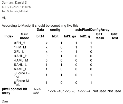
| Data | config | asicPixelConfigArray | |||||
|---|---|---|---|---|---|---|---|
| Index | Gain mode | bit14 | trbit | bit3: ga | bit2: g | bit1: Mask | bit0: Test |
| 0 | FH_H | x | 1 | 1 | 1 | ||
| 1 | FM_M | x | 0 | 1 | 1 | ||
| 2 | FL_L | x | x | 1 | 0 | ||
| 3 | AHL_H | 0 | 1 | 0 | 0 | ||
| 4 | AML_M | 0 | 0 | 0 | 0 | ||
| 5 | AHL_L | 1 | 1 | 0 | 0 | ||
| 6 | AML_L | 1 | 0 | 0 | 0 | ||
| 7 | AHL Forced L | 1 | 1 | 0 | 1 | ||
| 8 | AML Forced L | 1 | 0 | 0 | 1 | ||
| pixel control bit array | 1<<5 =32 | 1<<4 =16 | 1<<3 =8 | 1<<2 =4 | Not used | Not used | |
...
Overview
Content Tools