Table of Contents
Tools at SLAC: https://photos.app.goo.gl/uLpUdpsPU9Laigdp7
LBNL provided instructions for soldering leads to platinum heaters. Download yourself: LBNL PowerPoint Slides
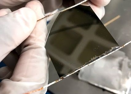
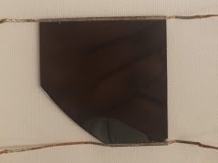
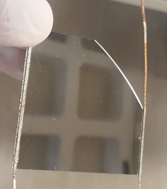
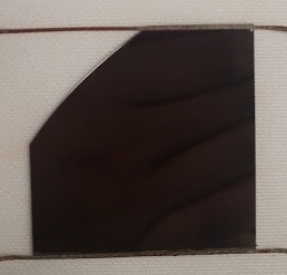
Note: The dummy heaters feature a shiny side -- a Pt thin film over an oxide layer. Their back sides are bare silicon, ground finish.
Mechanical drawings
Inventory
The table below is most likely out of date. For the 19-0 ring, please use this document as a reference (it collects all the info on the heaters wired and measured by Valentina and Sam in Jan 2020):
https://docs.google.com/spreadsheets/d/1s-4BwTW910EQzInhqSd7pgCI3uvk52Jl/edit#gid=2064913736
| Sample | Label | Dimension | Quantity | Who | Date |
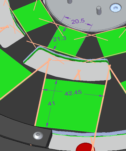
| Heaters single size | A19 | 21.3x20.5 | 9 | wired - Valentina | 4/14/21 |
| Heaters single size | B19 | 21.3x20.5 | 9 | wired - Valentina | 4/14/21 |
| Heaters quad size | C19 | 45x41 | 25 | wired - Valentina | 4/14/21 |
| Heaters dummies for tests (wafer edges) | D19 | 45x41 | 20 | wired - Valentina 10 - 6 to Zhi | 4/14/21 |
Heaters quad size Heaters single size | A21 10 boxes | TBC TBC | 25 87 | Caterina Caterina | 4/14/21 4/14/21 |
Dummy Heaters Inventory (the table above is a screenshot of 3/22). The latest status is at
Property measurements
Dimensions
Heaters dimensions have been measured here:
https://drive.google.com/drive/folders/1bW_r5Phgyt8DJJ4dwmBe-TeskERc6VYQ
And again here using the CMM:
https://docs.google.com/spreadsheets/d/184nDPdVxXGeM7emri5dYKY1ca4Y5buHXP0zP1pMPt3o/edit?usp=sharing
Electrical resistance
Resistance measurement of a single quad heater:
1.9 ohms
Soldering Procedures
Notebook PDF (HeaterSolderingPreparationNotebook.pdf) has the most up-to-date process information. – HH, JS, RH 2021
 HeaterSolderingPreparationNotebook.pdf
List of Materials:
1. Using cobar core solder 63/37 (Sn64 Pb37) type with flux core or.... the type of solder makes too much difference.
The diameter of the wire needs to be small 0.012" to 0.020".
2. The solder wick is either Solder-Wick by Chemtroncs. Or Hex-Wick by Hexacon Electric Co.
3. Liquid flux for between the wick and silicon.
The liquid flux defines where the solder will flow. Don't get the flux anywhere you don't want solder.
4. Alcohol for cleaning the flux from the fixtures after the soldering. A wood toothpick and cotton swab is useful to rub off some of the remaining flux.
Also, rinse the remaining wick with alcohol as it contains dry flux and looks nicer when it's cleaned off.
5. Heaters
6. Fixture to hold heaters and fixtures
7. Hot plate (to achieve 220C)
8. Protective equipment
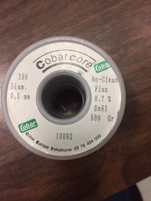
Cobar core solder 63/37 type with flux core
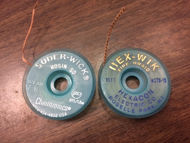
Solder-Wick by Chemtroncs (Left). Hex-Wick by Hexacon Electric Co.
List of Steps
(use photos for reference - NOTE: the "single" and "quad" modules are used interchangeably in the photos)
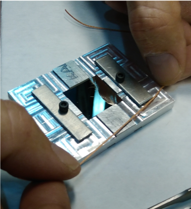
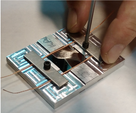
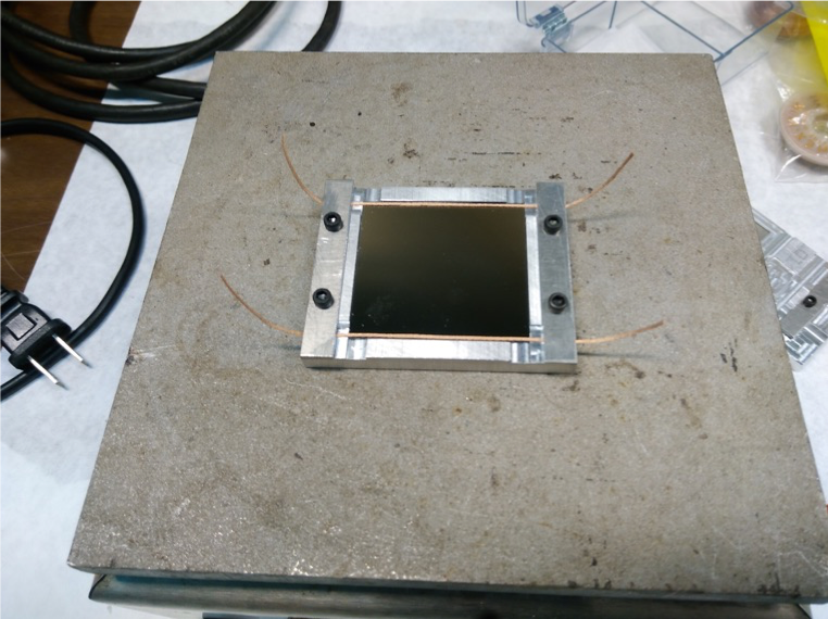
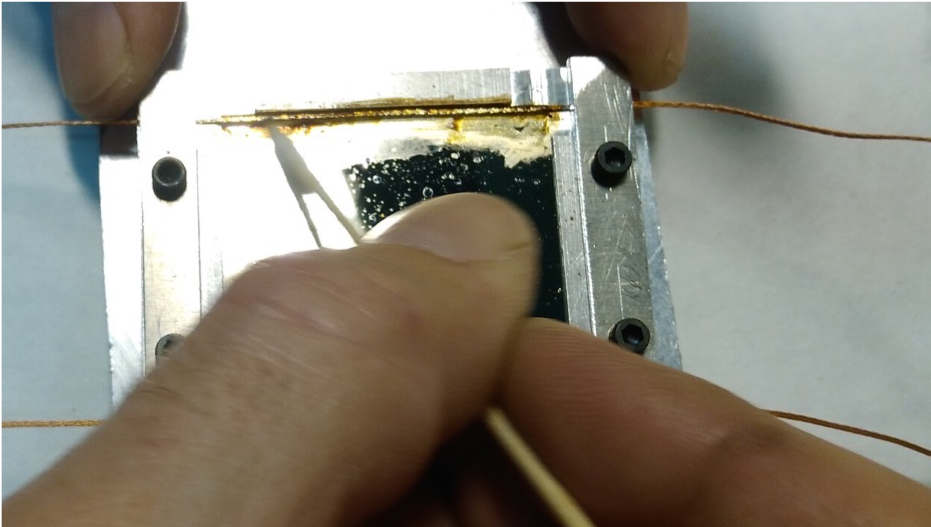
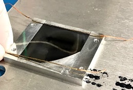
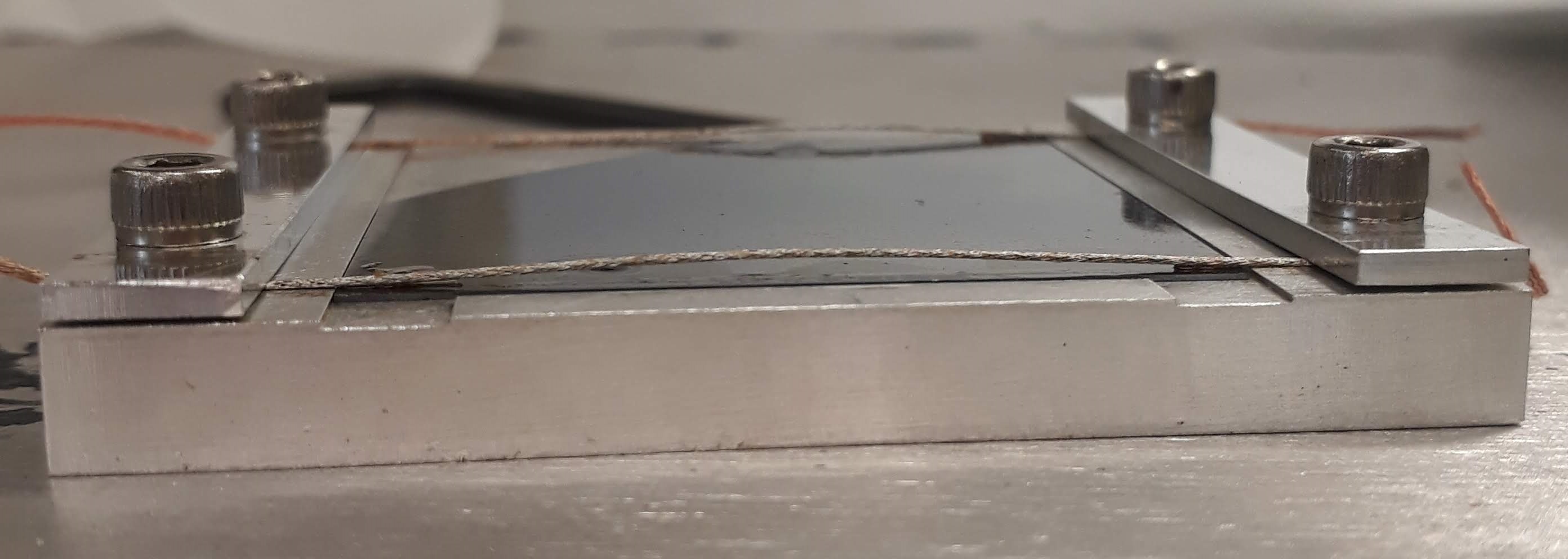
- Place heaters in the fixtures
- Align 2 solder wicks across the edge of the heater and hold them in place with the aluminum bar
- Fasten the aluminum bar down with the screw to keep the wick from moving
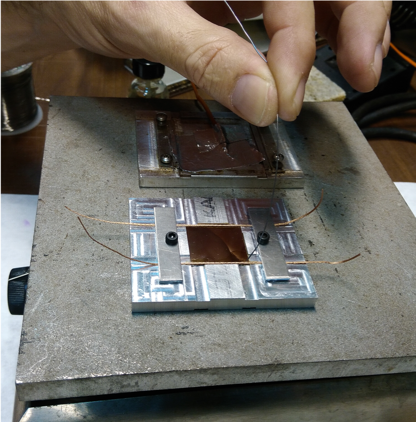
This step are illustrated in the photos here (for the quad modules):
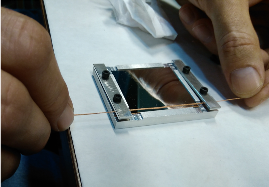
and for the single modules here:
- Once in the heater is assembled into the fixture place it on top of the hot plate
- Bring the hot plate up to 220 C
- When the aluminum fixture reaches the temperature of the hotplate: apply flux to the area between the solder wick and the heater
- Try to keep the flux contained to the location where the solder will go ("Don't get the flux anywhere you don't want solder")
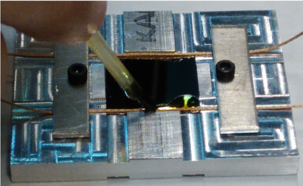
- Apply the solder to the area between the solder wick and the heater. (the solder wick should be 0.03 inches in diameter, the solder wire should be between 0.012 and 0.02 inches in diameter
- Once the solder is applied, turn off the hot plate and remove the fixture with the heater
- Wear protective gear!! Be careful: do not to touch the hot plate!!
- Let the solder cool
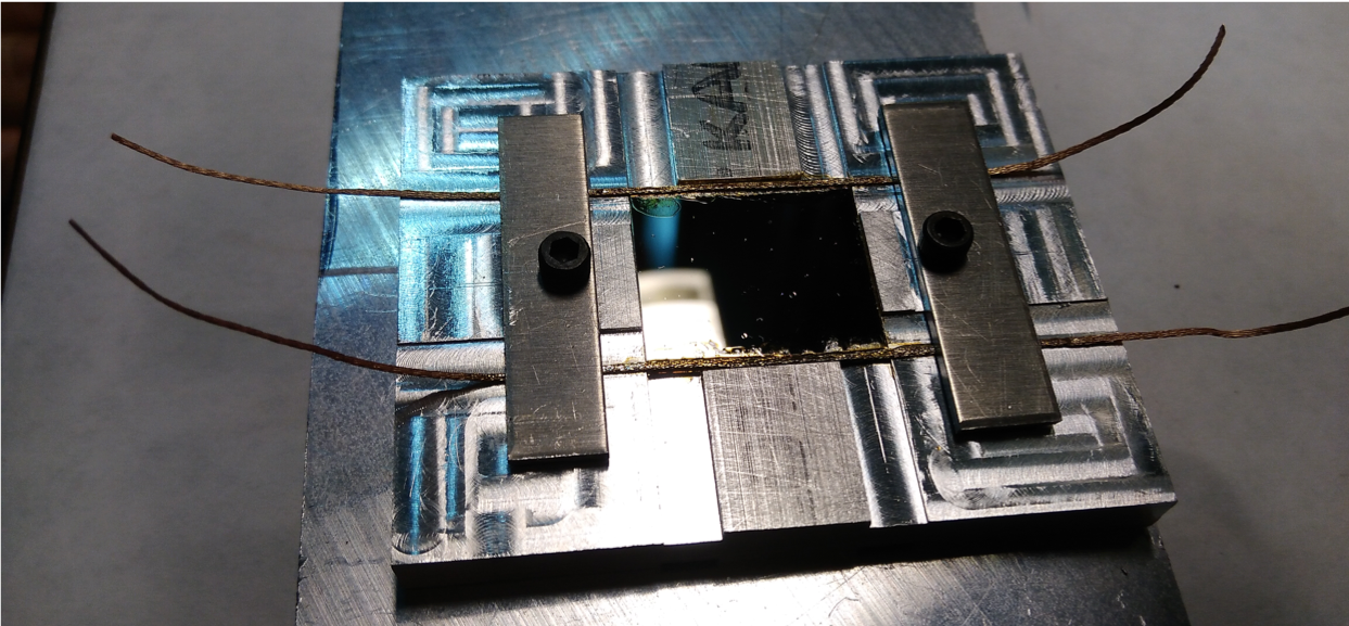
- Once the solder is cool clean the flux away with alcohol and a wooden q-tip stick
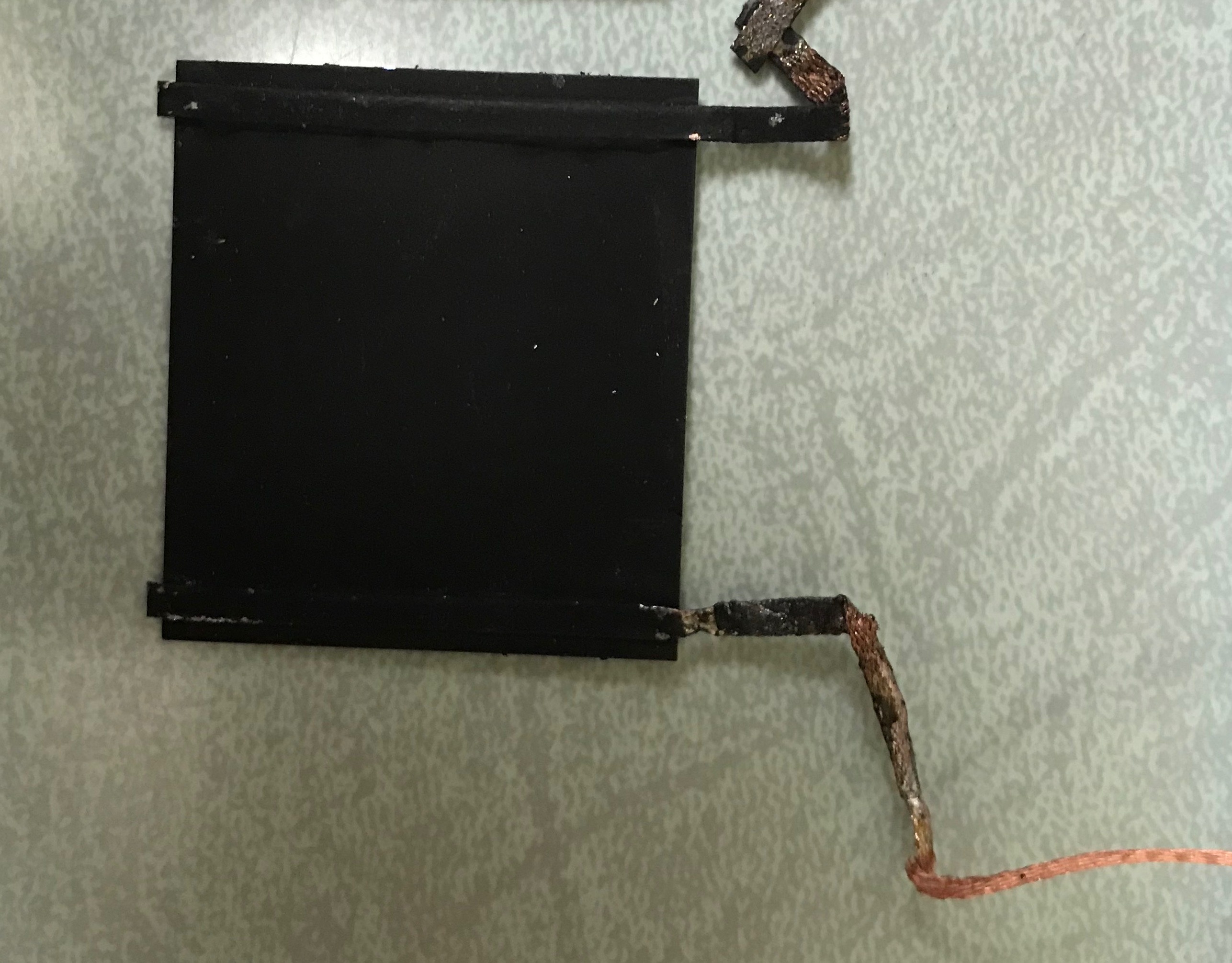
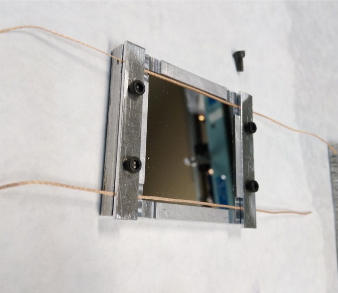
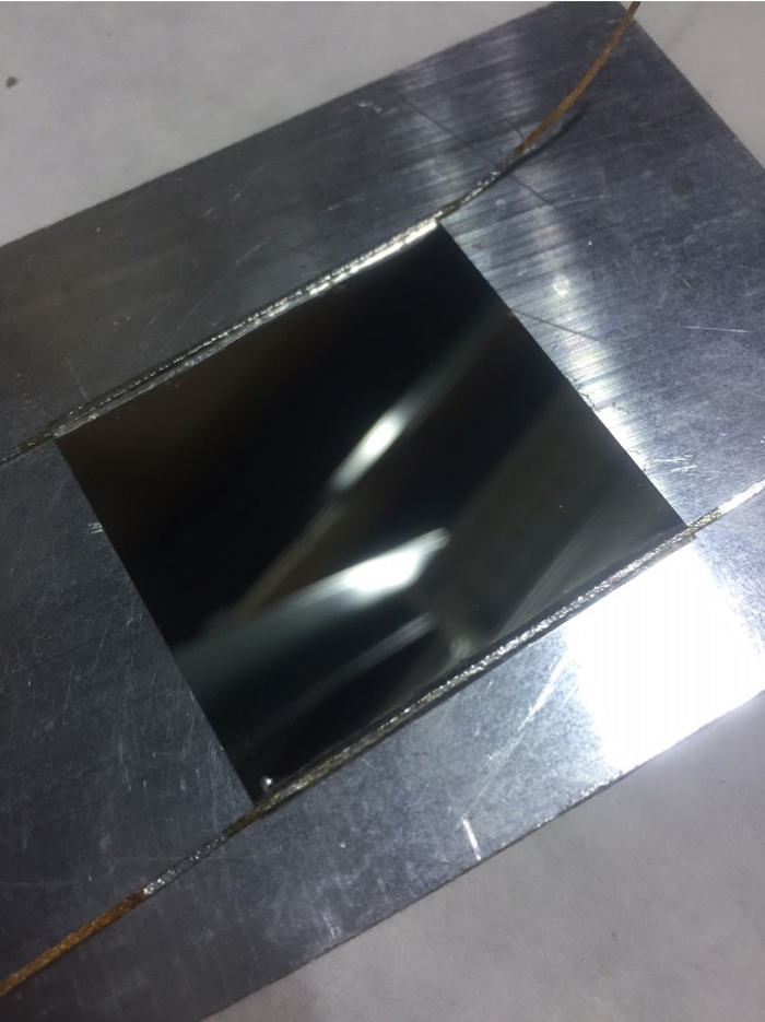
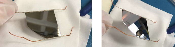
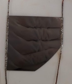
- Once complete the heater with the soldered on wicks will look like this:
Timed Process for mass implementation
Hot plate [10 mins to heat up + 10 mins to stabilize]
Turn on high setting.
Attach the thermal sensor to the aluminum rectangle ( below the washer)
Place the rectangle on the hot plate - make sure the wires don't bend and the electrical tape doesn't touch the aluminum.
In 10 mins check the temperature and if ~ 250 ℃ - turn the hot plate to 3.5 and let stabilize (fluctuations of ± 2 ℃)
Fixture setup [4-6 mins]
Clean the fixture ethanol
Lightly screw in the rectangles to the fixture
Cut the solder wick into ~8cm lengths
Set initial wire positions
Place the heater in the fixture in the right orientation (using a vacuum pen?)
Tighten the screws making sure the wires are in the right position
Clean the heaters with ethanol
Soldering [5 mins + 6 mins - actual soldering ]
Check the temperature ~ 245 ℃
Using 2 pliers place the fixture with the heaters on the hot plate
Wait ~4 mins for the fixture to come to the right temperature (it smells funky and smokes a bit)
Using the <0.02” diameter solder perform the actual soldering - be careful not to over solder
Clean up [15 mins]
Pick up the fixture with 2 pliers and place on the aluminum sheet
Wait 2 mins for the fixture to cool down
Use ethanol to clean up residue (napkins and Q-tips)
Undo the screws and rectangles
Remove the heater carefully (maybe vacuum pen will help here?) Sometimes the soldering makes the heaters stick to the fixture.
Place the heater in the wax cover and measure the resistance
Clean the fixture again to get it ready for the next heater.
Issues/Suggestions
How to avoid over soldering? Practice?
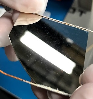
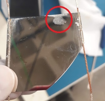
Speckles on the heaters after soldering - What are they?
Maybe some kind of support for Thanh?
How to label the heaters to record the resistance measurements? Mark the wax paper
Tests Performed
Test 1: May 2nd (Successful) [Spare Heater 1]
Spare heaters soldered at SLAC:
1st quad heater solder job:
Resistance for the spare quad heater: 3.5 ohms
Test 2: May 13th (Successful) [Spare Heater 2]
Resistance - 3.4 ohms
Issues -
- Speckling on the heater surface - Remained even after cleaning the surface with Alcohol - Maybe the flux spluttering and then baking on the heater surface
- Over Soldering - We requested Tan to use lesser solder in the process. Could also be because there was a small gap between the wick and the heater surface causing the solder to flow.
Test 3: May 14th (Not successful) [Spare Heater 3]
The wick just came off the heater without any force
Test 4: May 15th (Not successful) - Re-did the same heater as the above. [Spare Heater 3]
same issue - Wick just came off the heater.
Test 5: May 16th (Successful) - Re-did the same heater as above. [Spare Heater 3]
Why did it work this time?
- The heaters have a preferred side - There seems to be a blueish grey tinge on one side while the other is much more reflective. All the failed tests were set up to be soldered on the highly reflective side. The speckling from the flux that happened in the first 2 tests didn't happen on the "blue" side.
- Thanh soldered in between the wick and the heater
Issues - during the failed tests, the reflective side placed on the bottom was scratched.
Test 6: May 16th (Successful) [Spare Heater 4]
Resistance: 3.1 ohms
Test 7: May 22nd (Successful) [Spare Heater 5]
Resistance: 2.8 ohms
Test 8: May 24th (Successful) [Spare Heater 6]
Resistance: 3.5 ohms
Test 9: Jun 14th (Successful) [Spare heater 7]
Resistance: To be measured
Soldering: Aidan and Sam under Thanh's supervision
Test 10: Jun 14th (Successful) [Spare heater 8]
Resistance: To be measured
Soldering: Aidan and Sam
Stavelets
Old heaters were removed from stavelets to reload for radiation tests. They are different in dimension than the previous heaters. Their resistance distribution is as follows: Stavelet_heaters_Resistance_distribution.pdf
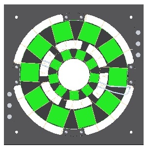
Dummy Heater position on 19-0 Ring
for reference:
- Ring Triplet, RD53a: https://edms.cern.ch/ui/file/2363540/1/RD53A_R0_Ring_Triplet.pdf
- Triplet chips have long edge in the radial direction.
- CAD view of 19-1 Ring with RD53a modules: https://confluence.slac.stanford.edu/download/attachments/245703318/DSG-000011081%20LOADED%20RING%2019-1.jpg?version=1&modificationDate=1610741454832&api=v2
- Quad modules have long edge in the tangential direction.
- ITk Clearances Drawing (reference for radial position): ITk_Clearances_Drawing_v1.9.5.pdf
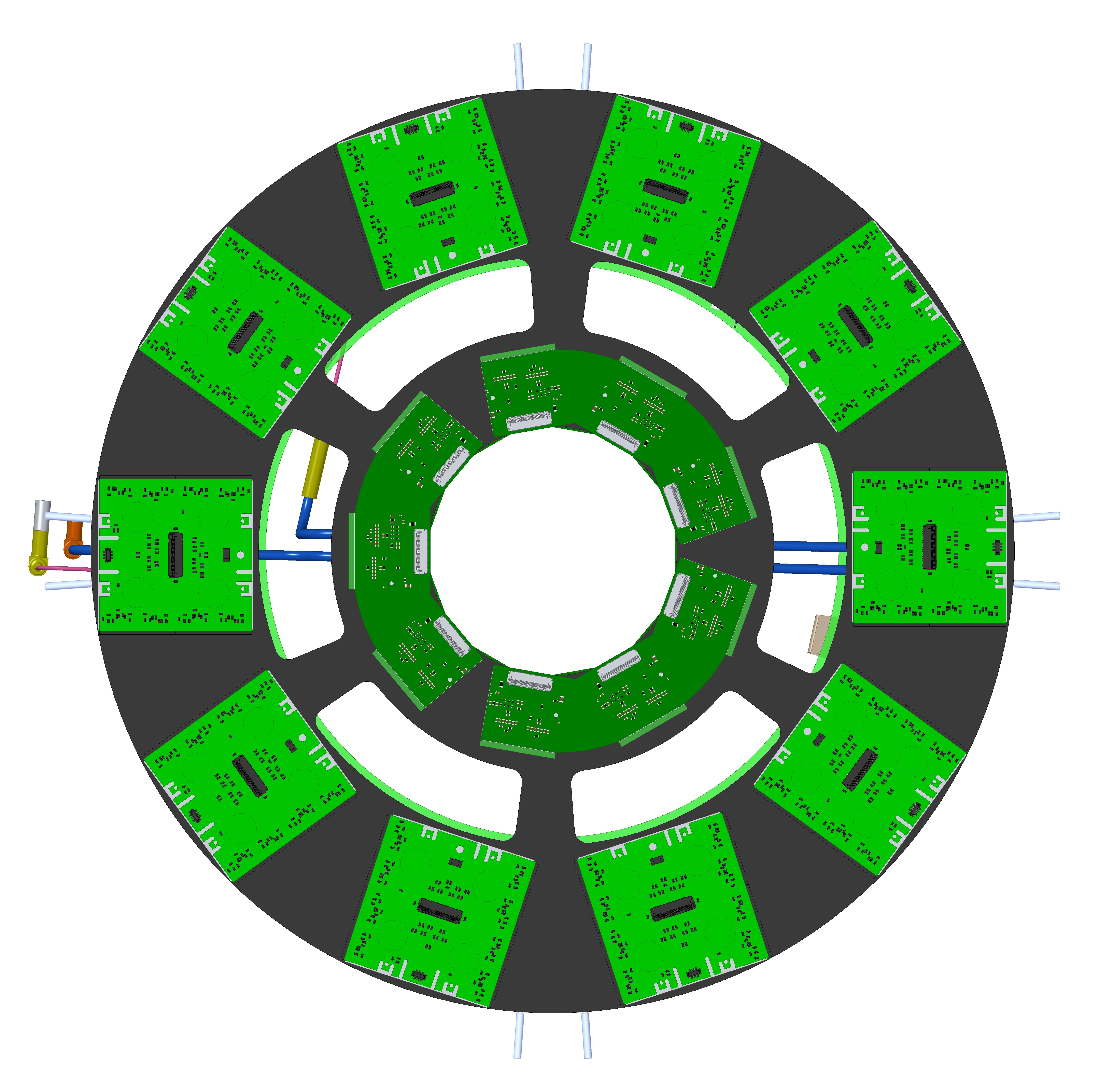
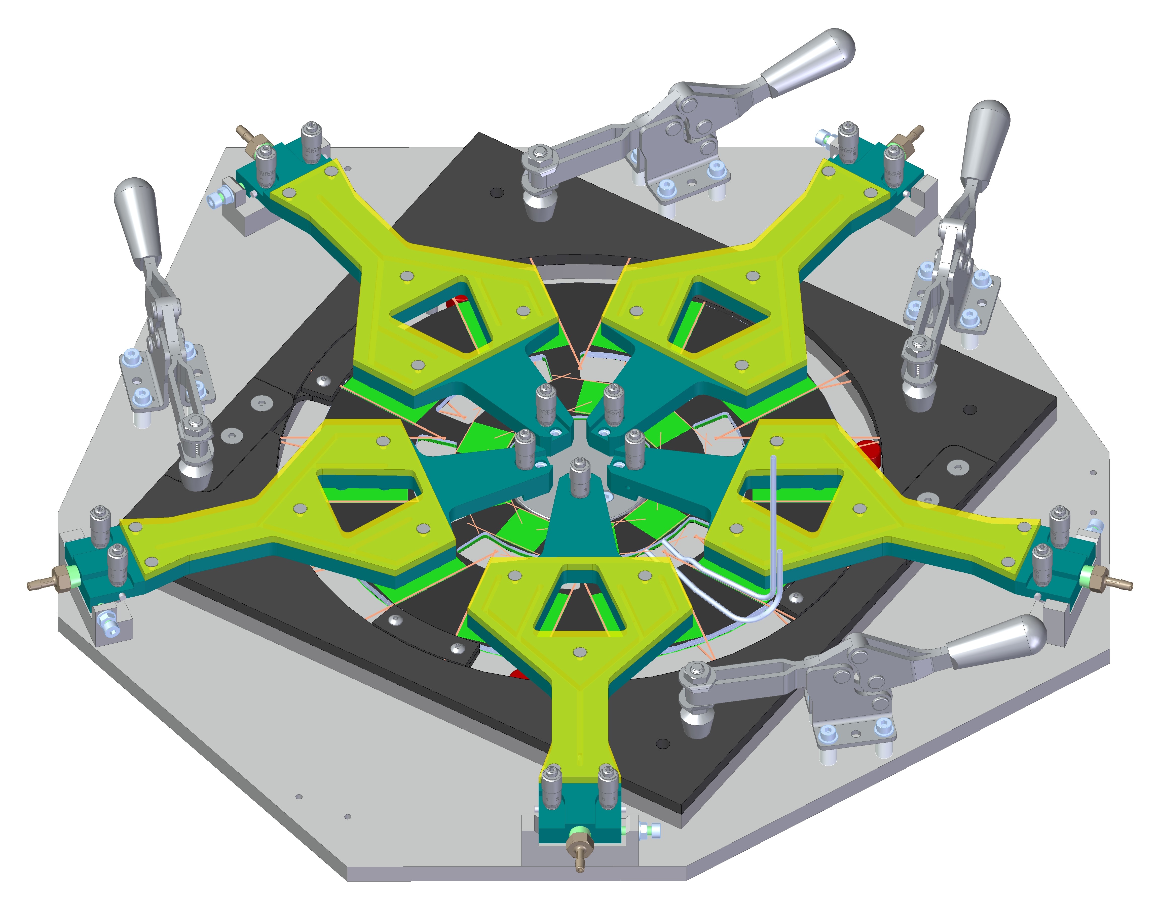
CAD views of Heaters and Ring:
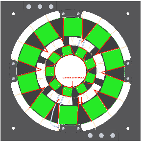
Wiring In Series – Heaters are to be wired together in series after loading onto the Ring.
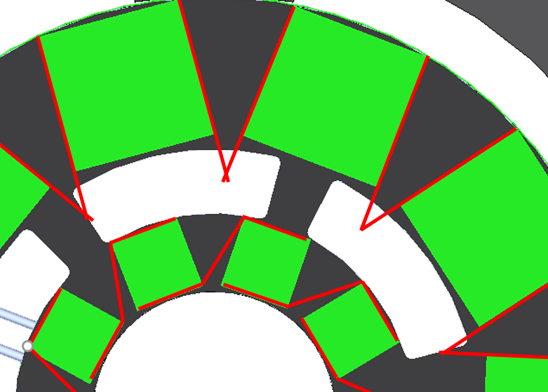
Connection for heaters on the ring: electrical circuit is given by the red and the green squares are the heaters. The red arrows are the position where the electric circuit connects to power supply