General FELIX Documentations
- FELIX user manual
- RD53A readout with FELIX and YARR system setup (ATL-COM-DAQ-2019-160))
- FLX-712 manual
- Interface board schematic
Related DAQ/Electronics Documentations
- GBT and Versatile Link: VLDB eSpace
- lpGBT and Versatile Link+: lpGBT, VLDB+
- VLDB schematic
- RD53a SCC schematic
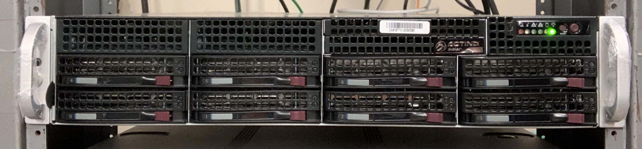
B33 Integration FELIX Setup
B84 FELIX Test Setup
|
 |
|---|---|
| |
|
FELIX Configuration Process
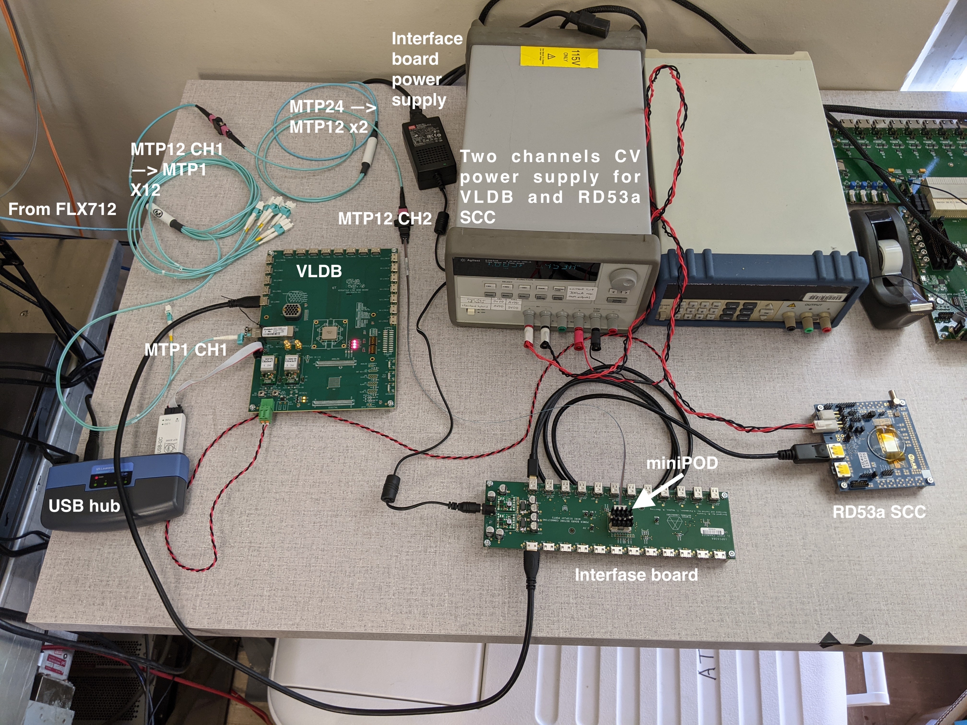
- Assemble the test stand according to figures from the "B84 FELIX Test Setup" section:
- Plug any of MTP12_CH1_STX cables where X = 1, 2, 3 or 4 (labeled as "1", "2", "3" or "4") into the VLDB's RX. Setup at SLAC uses X = 1.
- Plug mini-HDMI in G0-LinkX on VLDB, where X = 0, 2, 4 or 6. The X value will further be used as "TX" parameter in YARR configs.
- Use J77 for mini-HDMI and J93 for mini-DP on the interface board (more details in the board's schematics why). Mini-HDMI and mini-DP ports standing one against another are coupled.
- Configure VLDB (GUI is needed for java):
- Supply 5VCC with 1A limit in current to VLDB. With 5V input voltage a VLDB may consume as low as 300mA. Once the VLDB and FELIX configuration processes are done, the board consumes about 450mA.
- Use the .jar programmer file and the txt config file.
- In the command line run:
$ java -jar programmerv2.20180725.jar
(Java GUI will appear) - Click "import i..." in the top left corner and select the txt config file.
- Click "Write GBTX". After the process is done, GUI should look like the attached screenshot

- Update/install the most recent Felix firmware (assuming Vivado Lab is installed, and one has access to GUI):
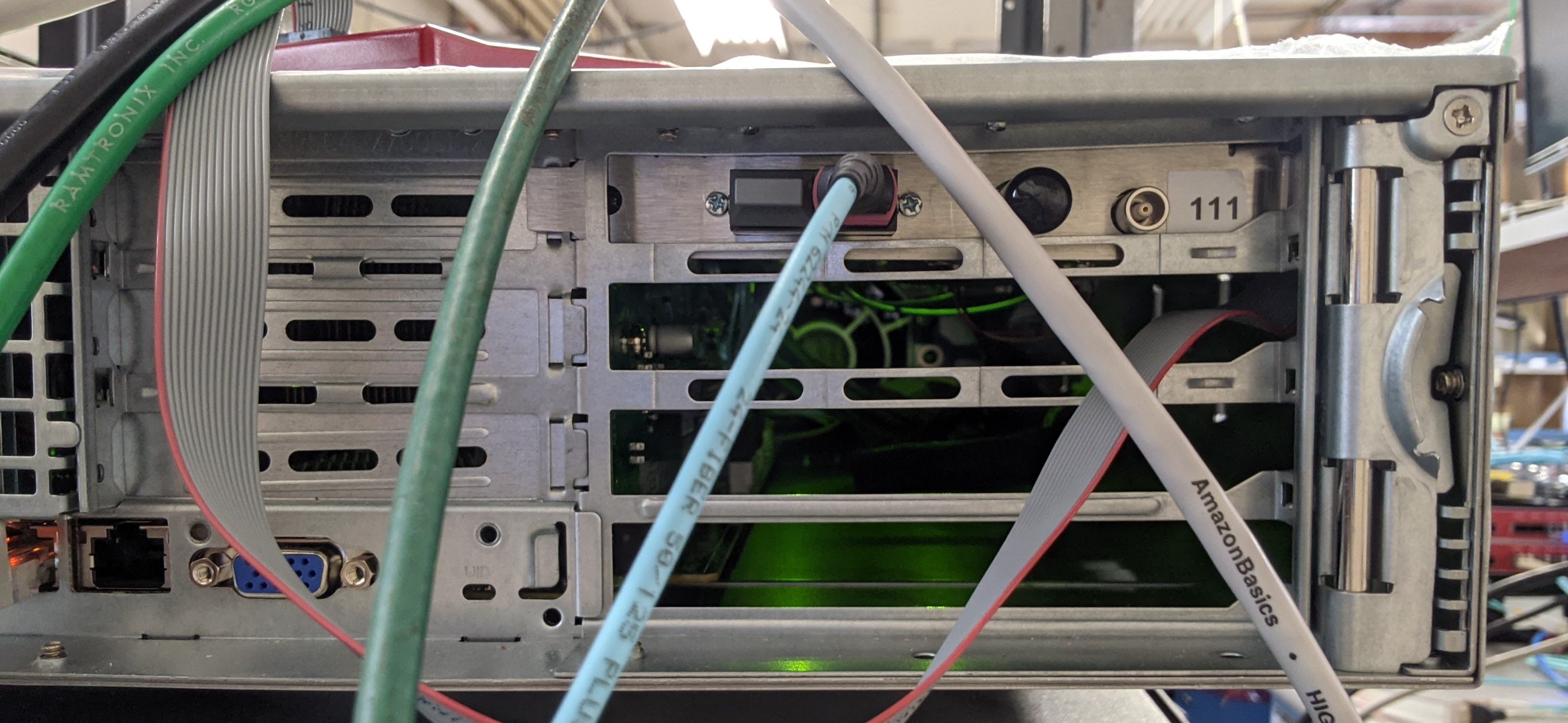
Plug in a JTAG-USB cable in a correct port on the FLX-712 board.

SLAC FLX-712 Board

ANL FLX-712 Diagram

Xilinx Dongle:
No LED light: PC doesn't see the dongle. Check drivers.
Yellow LED: No target. Check JTAG connections.
Green LED: Good! Can Proceed.
- Get Felix firmware from CERN Box.
- In Vivado Lab detect the target, use the .bit file to configure.
- Reboot the PC.
- Unplug the MTP12-CH1-TXA fiber from the VLDB and make sure you observe red light coming from the fiber. Plug in the fiber back to the VLDB's RX.
- If there is no GUI and/or Vivado on the Felix server, one may use an external PC to configure the FLX-712 board: keep the board in the server, plug the Xilinx USB dongle into the external PC and run Vivado from there.
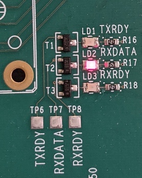
- Now you should see the RXDATA LED lighting with dim red color.
- Set up FELIX.
Depends on the number of FLX cards and their actual locations (PCIe ports) in your PC, option -c / -d in the following commands may vary. In the simplest case of one FLX card follow use same values as below.- Run from /home/USER/FELIX/felix-*/x86_64-centos7-gcc8-opt/
$ source "path_to_felix"/source.sh - Run from
$ flx-init -c0
Run the init command only once. If you run it twice or more in one session, you need to reboot the computer.
Get information about your FELIX:
$ flx-info -c0
May omit the info command, but it is useful to crocs-check that everything is ok. - Check polarity of the channels:
$ flx-config -d0 list | grep POLARITY
$ flx-config -d1 list | grep POLARITY
TX polarity must be inverted, otherwise readout is not possible.
If you observe "GBT-TXPOLARITY 0x000000000000", run:
$ flx-config -d1 set GBT-TXPOLARITY=0xffffffffffffffff
$ flx-config -d1 set GBT-TXPOLARITY=0xffffffffffffffff - If everything was done properly, the other two LEDs - TXRDY and RXRDY - should light up:

- Run from /home/USER/FELIX/felix-*/x86_64-centos7-gcc8-opt/
- Configure E-links in elinkconfig.
elinckconfig tool is described in the Felix manual - Section 6.1.
The procedure must be done after each system reboot.
TL;DR:- $ source "path_to_felix"/source.sh (if not done yet)
- $ elinkconfig
elinkconfig GUI appears:

Initial state of the elinkconfig

Target state of the elinkconfig
- Click "FULLmode" in the top panel. The left panel will collapse into just one box named "Enable FULLMODE": check the small box, and the entire block will turn orange.
- Check "TTC-to_Host (63b)" box in the top panel.
- Uncheck all the Epaths in the right panel: select "Egroup 0" on the bottom right, click "Disable" on the bottom right, click "Relp 2 All" on the bottom right; uncheck "EC (3f)" by hand.
- Click "2-bit" drop down button under the Egroup 0 and select "4-bit".
- Check Egroup0-EpathX according to your setup (G0-LinkX mini-HMDI ports on the VLDB).
Click "TH_FanOut..." on the top menu. New window will appear, click "None" and "OK". Repeat same for "FH_FanOut".

"ToHost FanOut" Initial state (same for "FromHost")

"ToHost FanOut" Target state (same for "FromHost")
- Click "Repl 2 All" on the top panel.
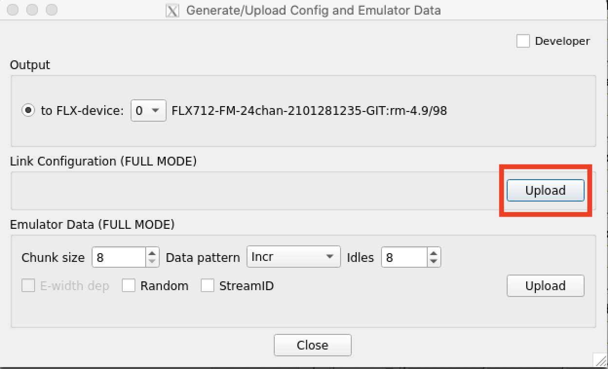
- Save the configuration: click "Generate/Update" on the top panels. new window will appear, click the top "Upload" button and "Close".
- Click "FLX-device" breakdown menu on the top panel, select 1 instead of 0. Repeat same procedure for the device 1. (NOTE: number of devices and their actual address depend on the number of FLX-712 cards used in a server. In case of one card use only 0 and 1.)
- Check some FELIX registers:
- flx-config -d0 list | grep GBT_GENERAL_CTRL
If returns other than 0x0000000000000004, run:
flx-config -d0 set GBT_GENERAL_CTRL=0x4 - flx-config -d0 list | grep GBT_ALIGNMENT_DONE
returns 0x0..f..0 when an RD53a SCC is connected (one "f" for each SCC). - flx-config -d0 list | grep GBT_RXCDR_LOCK
returns 0x0..f..0 when an RD53a SCC is connected (one "f" for each SCC).
- flx-config -d0 list | grep GBT_GENERAL_CTRL
Running YARR Scans with FELIX
Build YARR.
Get the correct version of YARR SW - to be updated.
...